MPU-6000 Просмотр технического описания (PDF) - Unspecified
Номер в каталоге
Компоненты Описание
производитель
MPU-6000 Datasheet PDF : 54 Pages
| |||
MPU-6000/MPU-6050 Product Specification
Document Number: PS-MPU-6000A-00
Revision: 3.3
Release Date: 5/16/2012
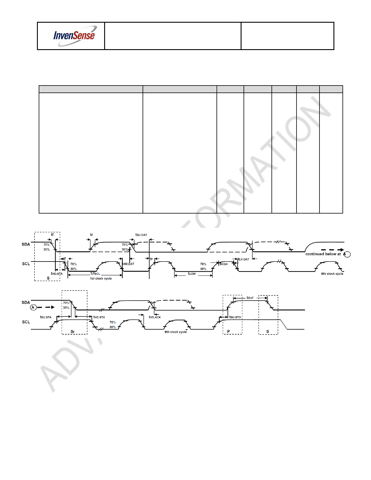
6.7 I2C Timing Characterization
Typical Operating Circuit of Section 7.2, VDD = 2.375V-3.46V, VLOGIC (MPU-6050 only) = 1.8V±5% or
VDD, TA = 25°C
Parameters
Conditions
Min
I2C TIMING
I2C FAST-MODE
fSCL, SCL Clock Frequency
tHD.STA, (Repeated) START Condition Hold
0.6
Time
tLOW, SCL Low Period
1.3
tHIGH, SCL High Period
0.6
tSU.STA, Repeated START Condition Setup
0.6
Time
tHD.DAT, SDA Data Hold Time
0
tSU.DAT, SDA Data Setup Time
100
tr, SDA and SCL Rise Time
tf, SDA and SCL Fall Time
tSU.STO, STOP Condition Setup Time
Cb bus cap. from 10 to 400pF
Cb bus cap. from 10 to 400pF
20+0.1Cb
20+0.1Cb
0.6
tBUF, Bus Free Time Between STOP and
1.3
START Condition
Cb, Capacitive Load for each Bus Line
tVD.DAT, Data Valid Time
tVD.ACK, Data Valid Acknowledge Time
Note: Timing Characteristics apply to both Primary and Auxiliary I2C Bus
Typical
< 400
Max
400
300
300
0.9
0.9
Units Notes
kHz
µs
µs
µs
µs
µs
ns
ns
ns
µs
µs
pF
µs
µs
I2C Bus Timing Diagram
18 of 54
Share Link: 