LC6514B Просмотр технического описания (PDF) - SANYO -> Panasonic
Номер в каталоге
Компоненты Описание
производитель
LC6514B
SANYO -> Panasonic

LC6514B Datasheet PDF : 17 Pages
| |||
LC6514B
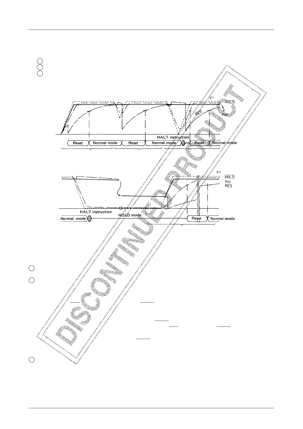
1-2. Operating waveform
The operating waveform in the sample application circuit in Fig. 11 is shown below. The mode is roughly divided
as follows.
1 Initial application of power
2 Instantaneous break
3 Return from backup mode
1-3. Operation of sample application circuit
1 At the time of initial application of power
A reset occurs and the execution of the program starts at address 000H of the program counter (PC).
2 At the time of instantaneous break
(1) At the time of very short instantaneous break
The execution of the program continues.
(2) At the time of instantaneous break being a little longer than (1)
(When the RES input voltage meets VIL and HOLD input voltage does not meet VIL)
A reset occurs during the execution of the program and the execution of the program starts at address 000H of
the program counter (PC).
Since the HOLD request signal is not applied to the HOLD pin, the HOLD mode is not entered.
(3) At the time of long instantaneous break (When both of the RES input voltage and HOLD input voltage meet
VIL)
The HOLD request signal is applied to the HOLD pin and the HOLD mode is entered.
When V+ rises after instantaneous break, a reset occurs to release the HOLD mode and the execution of the
program starts at address 000H of the program counter (PC).
3 At the time of return from backup voltage
A reset occurs and the execution of the program starts at address 000H of the program counter (PC).
No.1802–11/17
Share Link: