CY8C5246PVI-091 –ü—Ä–ĺ—Ā–ľ–ĺ—ā—Ä —ā–Ķ—Ö–Ĺ–ł—á–Ķ—Ā–ļ–ĺ–≥–ĺ –ĺ–Ņ–ł—Ā–į–Ĺ–ł—Ź (PDF) - Cypress Semiconductor
–Ě–ĺ–ľ–Ķ—Ä –≤ –ļ–į—ā–į–Ľ–ĺ–≥–Ķ
–ö–ĺ–ľ–Ņ–ĺ–Ĺ–Ķ–Ĺ—ā—č –ě–Ņ–ł—Ā–į–Ĺ–ł–Ķ
–Ņ—Ä–ĺ–ł–∑–≤–ĺ–ī–ł—ā–Ķ–Ľ—Ć
CY8C5246PVI-091 Datasheet PDF : 85 Pages
| |||
PRELIMINARY
PSoC¬ģ5: CY8C52 Family Data Sheet
4.1.1 Cortex-M3 Features
The Cortex-M3 CPU features include:
¬Ą 4 GB address space. Predefined address regions for code,
data, and peripherals. Multiple buses for efficient and simulta-
neous accesses of instructions, data, and peripherals.
¬Ą The Thumb¬ģ-2 instruction set, which offers ARM-level perfor-
mance at Thumb-level code density. This includes 16-bit and
32-bit instructions. Advanced instructions include:
‡ Bit-field control
‡ Hardware multiply and divide
‡ Saturation
‡ If-Then
‡ Wait for events and interrupts
‡ Exclusive access and barrier
‡ Special register access
The Cortex-M3 does not support ARM instructions.
¬Ą Bit-band support. Atomic bit-level write and read operations.
¬Ą Unaligned data storage and access. Contiguous storage of
data of different byte lengths.
¬Ą Operation at two privilege levels (privileged and user) and in
two modes (thread and handler). Some instructions can only
be executed at the privileged level. There are also two stack
pointers: Main (MSP) and Process (PSP). These features
support a multitasking operating system running one or more
user-level processes.
¬Ą Extensive interrupt and system exception support.
4.1.2 Cortex-M3 Operating Modes
The Cortex-M3 operates at either the privileged level or the user
level, and in either the thread mode or the handler mode.
Because the handler mode is only enabled at the privileged level,
there are actually only three states, as shown in Table 4-1.
Table 4-1. Operational Level
Condition
Privileged
Running an exception Handler mode
Running main program Thread mode
User
Not used
Thread mode
At the user level, access to certain instructions, special registers,
configuration registers, and debugging components is blocked.
Attempts to access them cause a fault exception. At the privi-
leged level, access to all instructions and registers is allowed.
The processor runs in the handler mode (always at the privileged
level) when handling an exception, and in the thread mode when
not.
4.1.3 CPU Registers
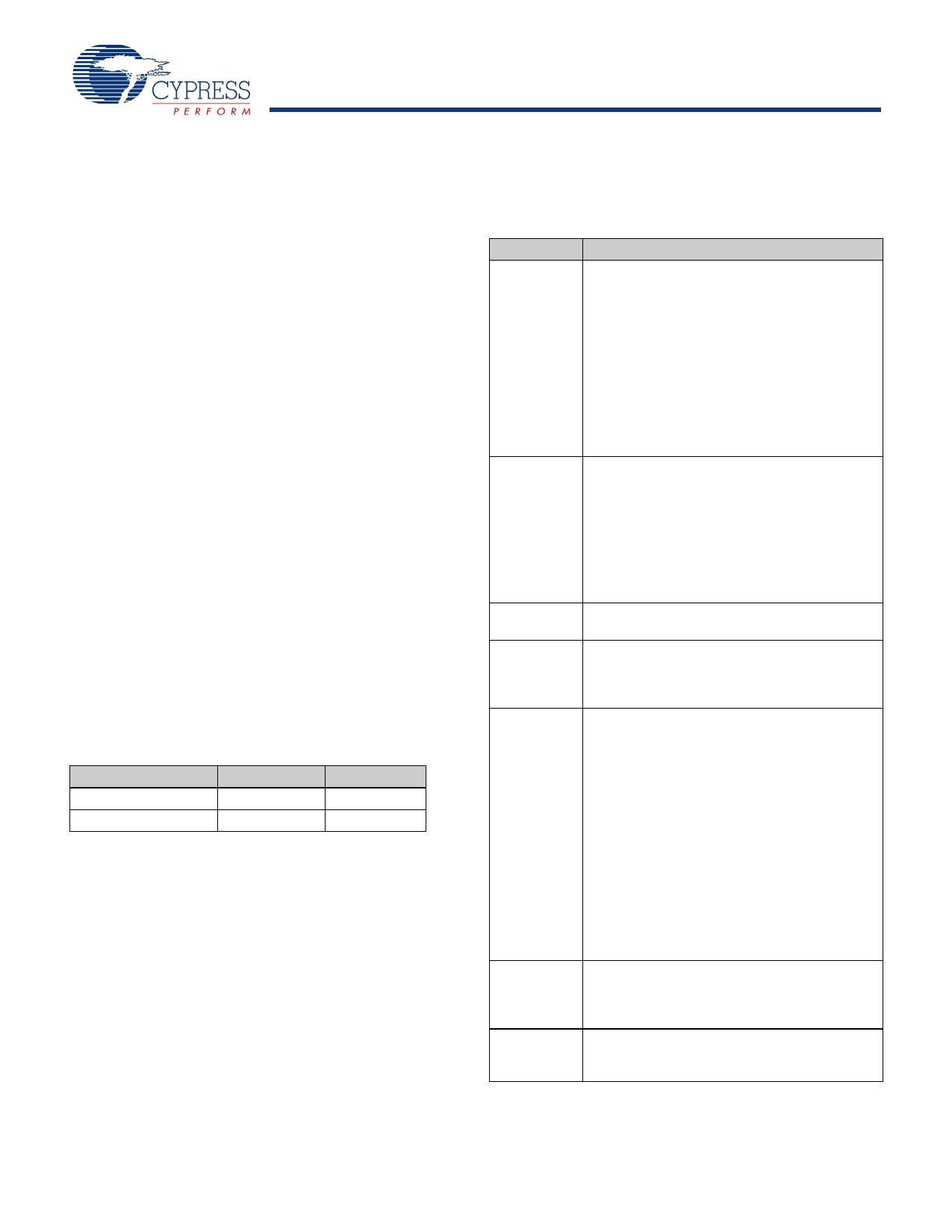
The Cortex-M3 CPU registers are listed in Table 4-2. Registers
R0-R15 are all 32 bits wide.
Table 4-2. Cortex M3 CPU Registers
Register
R0-R12
Description
General purpose registers R0-R12 have no
special architecturally defined uses. Most
instructions that specify a general purpose
register specify R0-R12.
¬Ą Low Registers: Registers R0-R7 are acces-
sible by all instructions that specify a general
purpose register.
¬Ą High Registers: Registers R8-R12 are acces-
sible by all 32-bit instructions that specify a
general purpose register; they are not acces-
sible by all 16-bit instructions.
R13
R13 is the stack pointer register. It is a banked
register that switches between two 32-bit stack
pointers: the Main Stack Pointer (MSP) and the
Process Stack Pointer (PSP). The PSP is used
only when the CPU operates at the user level in
thread mode. The MSP is used in all other
privilege levels and modes. Bits[0:1] of the SP
are ignored and considered to be 0, so the SP is
always aligned to a word (4 byte) boundary.
R14
R14 is the Link Register (LR). The LR stores the
return address when a subroutine is called.
R15
xPSR
R15 is the Program Counter (PC). Bit 0 of the PC
is ignored and considered to be 0, so instructions
are always aligned to a half word (2 byte)
boundary.
The Program status registers are divided into
three status registers, which are accessed either
together or separately:
¬Ą Application Program Status Register (APSR)
holds program execution status bits such as
zero, carry, negative, in bits[27:31].
¬Ą Interrupt Program Status Register (IPSR)
holds the current exception number in bits[0:8].
PRIMASK
¬Ą Execution Program Status Register (EPSR)
holds control bits for interrupt continuable and
IF-THEN instructions in bits[10:15] and
[25:26]. Bit 24 is always set to 1 to indicate
Thumb mode. Trying to clear it causes a fault
exception.
A 1-bit interrupt mask register. When set, it
allows only the nonmaskable interrupt (NMI) and
hard fault exception. All other exceptions and
interrupts are masked.
FAULTMASK A 1-bit interrupt mask register. When set, it
allows only the NMI. All other exceptions and
interrupts are masked.
Document Number: 001-55034 Rev. *A
Page 11 of 85
[+] Feedback
Share Link: 