82545GM Просмотр технического описания (PDF) - Intel
Номер в каталоге
Компоненты Описание
производитель
82545GM Datasheet PDF : 55 Pages
| |||
82545GM — Networking Silicon
3.4
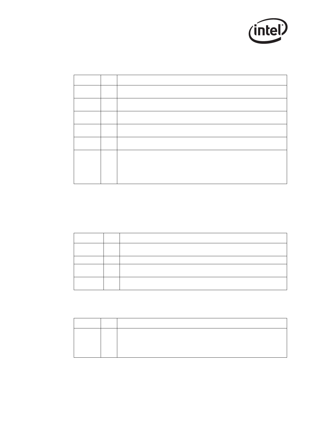
Flash Interface Signals
3.5
3.5.1
3.5.2
Symbol Type
Name and Function
FL_ADDR
[18:0]
O
FL_CS#
O
FL_OE# O
FL_WE# O
FL_DATA
[7:1]
TS
FL_DATA[0
]/LAN_
TS
DISABLE#
Flash Address Output. The Flash Address Output signals are used for a Flash or
Boot ROM device.
Flash Chip Select. The Flash Chip Select signal is used to enable the Flash or Boot
ROM device.
Flash Output Enable. The Flash Output Enable signal is used to enable the Flash
buffers.
Flash Write Enable Output. The Flash Write ENable Output signals are used for write
cycles.
Flash Data I/O. The Flash Data I/O signals are bi-directional and used for Flash data.
These signals include internal pull-up devices.
Flash Data I/O / LAN Disable. This pin is an input from the Flash memory.
Alternatively, the pin can be used to disable the LAN port from a system General Input
Output (GPIO) port. It has an internal pull-up device. If the 82545GM is not using Flash
functionality, the pin should be connected to external pull-up resistor.
If this pin is used as LAN_DISABLE, the device transitions to a low power state, and the
LAN port is disabled when this pin is sampled low on the rising edge of PCI reset.
Miscellaneous Signals
LED Signals
Symbol
ACT#
LINK#
LINK100#
LINK1000#
Type
Name and Function
O
Activity. The Activity LED signal flashes an LED to indicate receive activity on the
Ethernet port for packets only destined to this node.
O
Link. The Link LED signal indicates link connectivity on the Ethernet port.
O
Link 100. The Link 100 signal drives an LED indicating link at 100 Mbps on the
Ethernet port.
O
Link 1000. The Link 1000 signal drives an LED indicating link at 1000 Mbps on the
Ethernet port.
Software Definable Signals
Symbol
SDP[7:6]
SDP[1:0]
Type
Name and Function
Software Defined Pin. The Software Defined Pins are reserved and programmable
with respect to input and output capability. These default to input signals upon power-
TS up but may be configured differently by the EEPROM. The upper four bits may be
mapped to the General Purpose Interrupt bits if they are configured as input signals.
Note: SDP5 is not included in the group of Software Defined Pins.
14
Datasheet
Share Link: 