IDT82P2281 Просмотр технического описания (PDF) - Integrated Device Technology
Номер в каталоге
Компоненты Описание
производитель
IDT82P2281 Datasheet PDF : 375 Pages
| |||
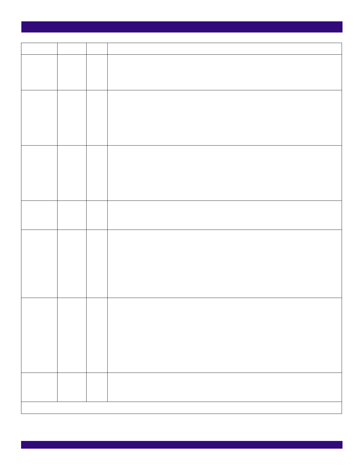
IDT82P2281
SINGLE T1/E1/J1 LONG HAUL / SHORT HAUL TRANSCEIVER
Name
Type Pin No.
Description
CS
Input
38 CS: Chip Select (Active Low)
This pin must be asserted low to enable the microprocessor interface. The signal must be asserted high at least once
after power up to clear the internal test modes. A transition from high to low must occur on this pin for each Read/Write
operation and can not return to high until the operation is completed.
CS is a Schmitt-trigger input.
A[0]
Input
41 A[7:0]: Address Bus
A[1]
42 In parallel mode, the signals on these pins select the register for the microprocessor to access.
A[2]
43 In SPI mode, these pins should be connected to the ground.
A[3]
44 A[7:0] are Schmitt-trigger inputs with pull-down resistor.
A[4]
45
A[5]
46
A[6]
49
A[7]
51
D[0] / SDO Output / Input 24 D[7:0]: Bi-directional Data Bus
D[1]
25 In parallel mode, the signals on these pins are the data for Read / Write operation.
D[2]
26 In SPI mode, the D[7:1] pins should be connected to the ground through a 10 K resistor.
D[3]
27 D[7:0] are Schmitt-trigger inputs/outputs.
D[4]
28
D[5]
29 SDO: Serial Data Output
D[6]
31 In SPI mode, the data is serially output on this pin.
D[7]
33
MPM
Input
RW / WR / SDI
Input
22 MPM: Micro Controller Mode
In parallel mode, set this pin low for Motorola mode or high for Intel mode.
In SPI mode, set this pin to a fixed level (high or low). This pin is useless in SPI mode.
MPM is a Schmitt-trigger input.
37 RW: Read / Write Select
In parallel Motorola mode, this pin is active high for read operation and active low for write operation.
WR: Write Strobe (Active Low)
In parallel Intel mode, this pin is active low for write operation.
SDI: Serial Data Input
In SPI mode, the address/control and/or data are serially input on this pin.
DS / RD / SCLK Input
RW / WR / SDI is a Schmitt-trigger input.
36 DS: Data Strobe (Active Low)
In parallel Motorola mode, this pin is active low.
RD: Read Strobe (Active Low)
In parallel Intel mode, this pin is active low for read operation.
SCLK: Serial Clock
In SPI mode, this pin inputs the timing for the SDO and SDI pins. The signal on the SDO pin is updated on the falling
edge of SCLK, while the signal on the SDI pin is sampled on the rising edge of SCLK.
SPIEN
DS / RD / SCLK is a Schmitt-trigger input.
Input
23 SPIEN: Serial Microprocessor Interface Enable
When this pin is low, the microprocessor interface is in parallel mode.
When this pin is high, the microprocessor interface is in SPI mode.
SPIEN is a Schmitt-trigger input.
JTAG (per IEEE 1149.1)
Pin Description
7
October 7, 2003
Share Link: 