LRI512 Просмотр технического описания (PDF) - STMicroelectronics
Номер в каталоге
Компоненты Описание
производитель
LRI512
STMicroelectronics

LRI512 Datasheet PDF : 54 Pages
| |||
LRI512
TIMING DEFINITION
t1: LRI512 Response Delay
t1 is as defined in Table 19.
Upon detection of the rising edge of the EOF re-
ceived from the VCD, the LRI512 wait for a time
equal to
t1(typ) = 4352/fC (see Table 59)
before starting to transmit its response to a VCD
request or switch to the next slot when in an inven-
tory process.
The EOF is defined in page 7.
t2: VCD New Request Delay
t2 is the time after which the VCD may send an
EOF to switch to the next slot when one or more
LRI512 responses have been received during an
inventory command. It starts from the reception of
the EOF received from the LRI512s.
The EOF sent by the VCD may be either 10% or
100% modulated independent of the modulation
index used for transmitting the VCD request to the
LRI512.
t2 is also the time after which the VCD may send a
new request to the LRI512 as described in Figure
29., LRI512 Protocol Timing, on page 16.
t2(min) = 4192/fC (see Table 59)
t3: VCD New Request Delay when No LRI512
Response
t3 is the time after which the VCD may send an
EOF to switch to the next slot when no LRI512 re-
sponse has been received.
The EOF sent by the VCD may be either 10% or
100% modulated independent of the modulation
index used for transmitting the VCD request to the
LRI512.
From the time the VCD has generated the rising
edge of an EOF:
– If this EOF is 100% modulated, the VCD shall
wait a time at least equal to t3minimum before
sending a subsequent EOF.
– If this EOF is 10% modulated, the VCD shall
wait a time at least equal to the sum of t3minimum
+ the nominal response time of a LRI512, which
depend on the LRI512 data rate and subcarrier
modulation mode before sending a subsequent
EOF.
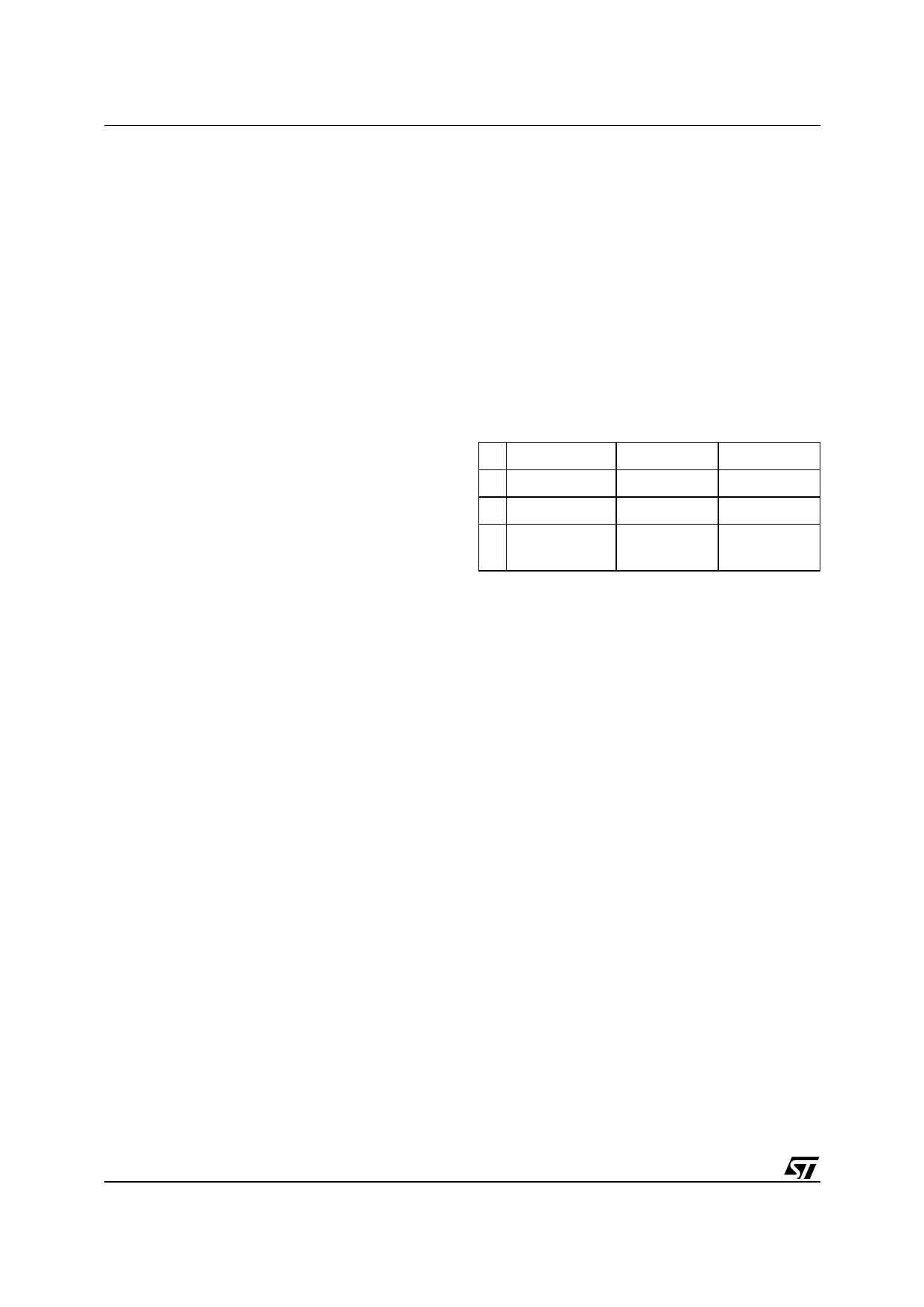
Table 19. Timing Values (see Table 59)
Min.
Nominal
Max.
t1
t1(min)
t1(typ)
t1(max)
t2
t2(min)
—
—
t3
t1(max) + tSOF
(notes1,2)
—
—
Note: 1. tSOF is the duration for the LRI512 to transmit an SOF to
the VCD. tSOF is dependant on the current data rate:
High data rate or Low data rate.
2. t1(max) does not apply for write alike requests. Timing
conditions for write alike requests are defined in the com-
mand description.
3. The tolerance of specific timings is ± 32/fC.
26/54
Share Link: