LF3370 Просмотр технического описания (PDF) - LOGIC Devices
Номер в каталоге
Компоненты Описание
производитель
LF3370 Datasheet PDF : 24 Pages
| |||
DEVICES INCORPORATED
LF3370
High-Definition Video Format Converter
and interleaved video is presented to input
port B12-0 (i.e., Chroma). The input
demultiplexer, in this case, separates video
data on B12-0 and outputs two channels of
separated video into the LF3370 core with
a delay of 4 CLK cycles. For this operation,
bit 0 must be set to 0 and bit 1 must be set to
1 in Configuration Register 0 (see Table 5).
If 4:2:2 video data is on one channel
interleaved (see Figure 5), it is assumed
that interleaved video is presented to input
port A12-0. The input demultiplexer, in
this case, separates video data on A12-0
and outputs three channels of separated
video into the LF3370 core with a delay of
5 CLK cycles. In this case, the core will
run at half of the CLK rate and valid data
will be output at at half of the CLK rate.
For this operation, bit 0 must be set to 1
and bit 1 must be set to 0 in Configuration
Register 0 (see Table 5).
All input demultiplexing operations are
controlled by the latched HIGH to LOW
transitions of SYNC which synchronizes
the LF3370 core to the multiplexed input
data (see SYNC discussion). It is impor-
tant that unused input ports be set either
HIGH or LOW.
Output Multiplexer
The output multiplexer section can be
configured in various ways to accommo-
date the video system. Bits 2 and 3 of
Configuration Register 0 determines the
number of output channels that the
LF3370 will drive. Z12-0 is the Key
channel output port; the Key channel
simply gets passed through the output
multiplexer with a latency that matches
the other three channels.
If three separate output channels of non-
interleaved video are desired, no multi-
plexing is performed. The three channels
are passed through the output multi-
plexer unmodified on the output ports
W12-0, X12-0, and Y12-0 with a delay of 2
CLK cycles. For this operation, bits 2 and
3 must both be set to 1 in Configuration
Register 0 (see Table 5).
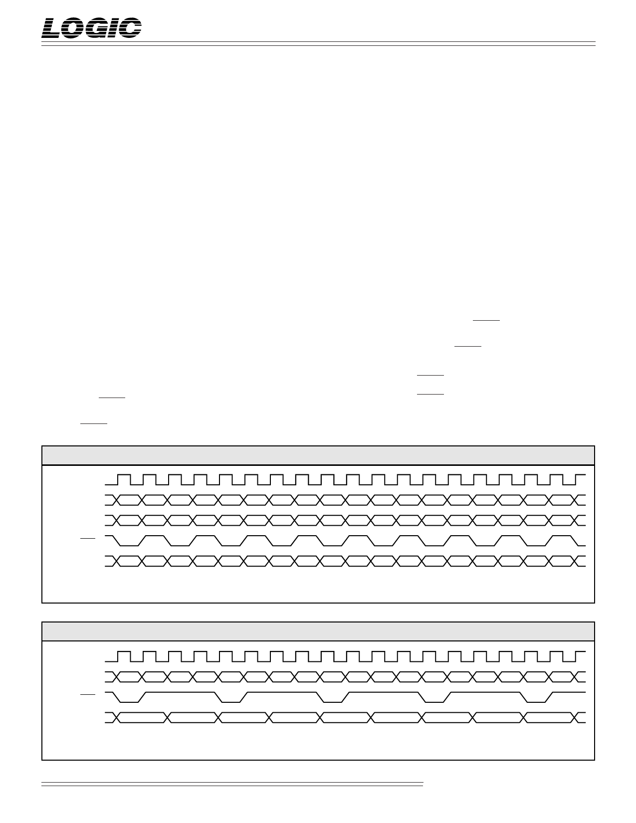
If one channel of non-interleaved video
(i.e., Luma) and one channel of inter-
leaved video (i.e., Chroma) is desired (see
Figure 6), non-interleaved video will be
driven to the output port W12-0 and
interleaved video will be driven to the
output port X12-0 with a delay of 2 CLK
cycles. For this operation, bit 2 must be set
to 0 and bit 3 must be set to 1 in Configu-
ration Register 0 (see Table 5).
If 4:2:2 interleaved video on one port is
desired (see Figure 7), interleaved video
will be driven to the output port W12-0
with a delay of 4 CLK cycles. For this
operation, bit 2 must be set to 1 and bit 3
must be set to 0 in Configuration Register 0
(see Table 5).
All output multiplexing operations are
initiated by the latched HIGH to LOW
transitions of SYNC which synchronizes
the multiplexed output data to the LF3370
core (see SYNC discussion).
SYNC
SYNC control signal is required to
properly synchronize the input
demultiplexer, output multiplexer, and
FIGURE 6. OUTPUTTING 4:2:2:4 (INTERLEAVED CHROMA ON CHANNEL X)
CLK
W12-0
Y0
Y1
Y2
Y3
Y4
Y5
Y6
Y7
Y8
Y9 Y10 Y11 Y12 Y13 Y14 Y15 Y16 Y17
X12-0
CB0 CR0 CB2 CR2 CB4 CR4 CB6 CR6 CB8 CR8 CB10 CR10 CB12 CR12 CB14 CR14 CB16 CR16
Y0 (Output SYNC)*
Z12-0
K0
K1
K2
K3
K4
K5
K6
K7
K8
K9 K10 K11 K12 K13 K14 K15 K16 K17
* There will be a HIGH to LOW transition on every Cb sample
FIGURE 7. OUTPUTTING 4:2:2:4 (INTERLEAVED LUMA/CHROMA ON CHANNEL W)
CLK
W12-0
CB0 Y0 CR0 Y1 CB2 Y2 CR2 Y3 CB4 Y4 CR4 Y5 CB6 Y6 CR6 Y7 CR8 Y8
Y0 (Output SYNC)*
Z12-0
K0
K1
K2
K3
K4
K5
K6
K7
K8
* There will be a HIGH to LOW transition on every Cb sample
Video Imaging Products
7
03/13/2001–LDS.3370-F
Share Link: 