X28C010D Просмотр технического описания (PDF) - Intersil
Номер в каталоге
Компоненты Описание
производитель
X28C010D Datasheet PDF : 23 Pages
| |||
X28C010
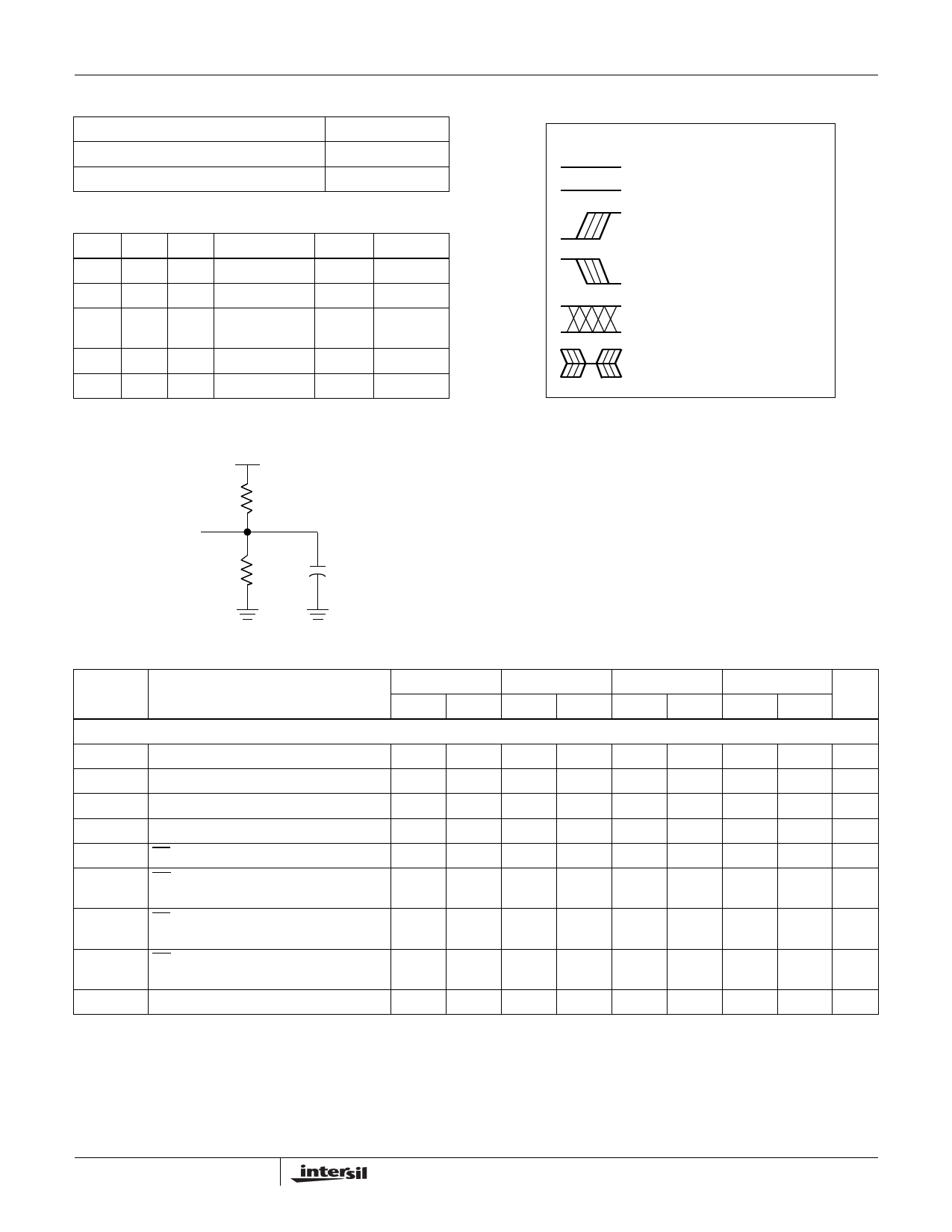
A.C. Conditions of Test
Input pulse levels
Input rise and fall times
Input and output timing levels
0V to 3V
10ns
1.5V
Mode Selection
CE OE WE
MODE
L
L
H
Read
L
H
L
Write
H
X
X
Standby and
Write Inhibit
X
L
X
Write Inhibit
X
X
H
Write Inhibit
I/O
DOUT
DIN
High Z
—
—
POWER
Active
Active
Standby
—
—
Equivalent A.C. Load Circuit
5V
Symbol Table
WAVEFORM INPUTS
OUTPUTS
Must be
steady
Will be
steady
May change
from LOW
to HIGH
May change
from HIGH
to LOW
Don’t Care:
Changes
Allowed
N/A
Will change
from LOW
to HIGH
Will change
from HIGH
to LOW
Changing:
State Not
Known
Center Line
is High
Impedance
1.92kΩ
Output
1.37kΩ
100pF
AC Electrical Specifications Over the recommended operating conditions, unless otherwise specified.
X28C010-12
X28C010-15
X28C010-20
SYMBOL
PARAMETER
MIN MAX MIN MAX MIN MAX
READ CYCLE LIMITS
tRC
Read cycle time
tCE
Chip enable access time
tAA
Address access time
tOE
Output enable access time
tLZ (Note 3) CE LOW to active output
tOLZ OE LOW to active output
(Note 3)
120
150
200
120
150
200
120
150
200
50
50
50
0
0
0
0
0
0
tHZ
CE HIGH to high Z output
(Note 3)
50
50
50
tOHZ OE HIGH to high Z output
(Note 3)
50
50
50
tOH
Output hold from address change
0
0
0
X28C010-25
MIN MAX
UNIT
250
ns
250
ns
250
ns
50
ns
0
ns
0
ns
50
ns
50
ns
0
ns
11
FN8105.0
May 11, 2005
Share Link: 