TDA7562 Просмотр технического описания (PDF) - STMicroelectronics
Номер в каталоге
Компоненты Описание
производитель
TDA7562 Datasheet PDF : 17 Pages
| |||
TDA7562
MULTIPLE FAULTS.
When more misconnections are simultaneously in
place at the audio outputs, it is guaranteed that at
least one of them is initially read out. The others
are notified after successive cycles of I2C reading
and faults removal, provided that the diagnostic is
enabled.
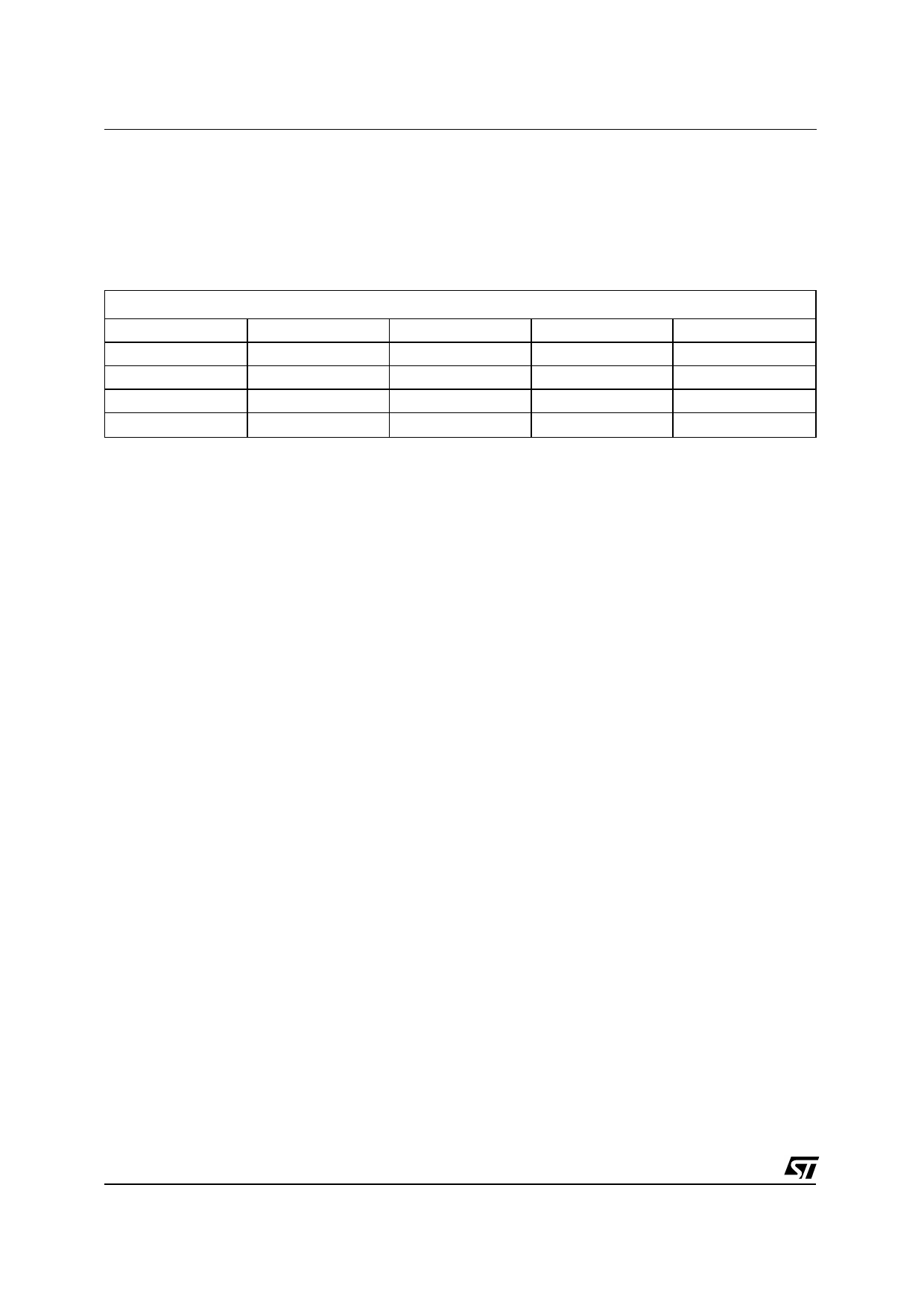
The table below shows all the couples of double-
fault possible. It should be taken into account that
a short circuit with the 4 ohm speaker uncon-
nected is considered as double fault.
Double fault table for Diagnostics
S. GND (so)
S. GND (so)
S. GND
S. GND (sk)
/
S. Vs
/
S. Across L.
/
S. GND (sk)
S. GND
S. GND
/
/
S. Vs
S. Vs + S. GND
S. Vs
S. Vs
/
S. Across L.
S. GND
S. GND
S. Vs
S. Across L.
S. GND (so) / S. GND (sk) in the above table
make a distinction according to which of the 2
outputs is shorted to ground (test-current source
side= so, test-current sink side = sk). More pre-
cisely, so = CH+, sk = CH-.
FAULTS AVAILABILITY
All the results coming from I2Cbus, by read opera-
tions, are the consequence of measurements in-
side a defined period of time. If the fault is stable
throughout the whole period, it will be sent out.
To guarantee always resident functions, every
kind of diagnostic cycles will be reactivate after
any I2C reading operation. So, when the micro
reads the I2C, a new cycle will be able to start, but
the read data will come from the previous diag.
cycle (i.e. The device is in turned On, with a short
to Gnd, then the short is removed and micro
reads I2C. The short to Gnd is still present in
bytes, because it is the result of the previous cy-
cle. If another I2C reading operation occurs, the
bytes do not show the short). In general to ob-
serve a change in Diagnostic bytes, two I2C
reading operations are necessary.
I2C PROGRAMMING/READING SEQUENCE
A correct turn on/off sequence respectful of the di-
agnostic timings and producing no audible noises
could be as follows (after battery connection):
TURN-ON: PIN2 > 7V --- 10ms --- (STAND-BY
OUT + DIAG ENABLE) --- 500 ms (min) --- MUT-
ING OUT
TURN-OFF: MUTING IN --- 20 ms --- (DIAG DIS-
ABLE + STAND-BY IN) --- 10ms --- PIN2 = 0
Car Radio Installation: PIN2 > 7V --- 10ms DIAG
ENABLE (write) --- 200 ms --- I2C read (repeat
until All faults disappear).
OFFSET TEST: Device in Play (no signal) --
OFFSET ENABLE - 30ms - I2C reading
(repeat I2C reading until high-offset message dis-
appears).
10/17
Share Link: 