STF202-22T1G Просмотр технического описания (PDF) - ON Semiconductor
Номер в каталоге
Компоненты Описание
производитель
STF202-22T1G Datasheet PDF : 6 Pages
| |||
STF202−22T1G
As previously mentioned, there are two types of
configurations for the USB port which are upstream and
downstream. If your port connects to the host either in a
direct way or through a hub, you are upstream (data flows
“up” to the host) and in the other hand, if you are the host or
your port provides access to the host then you are
downstream (data flows “down” from the host to the
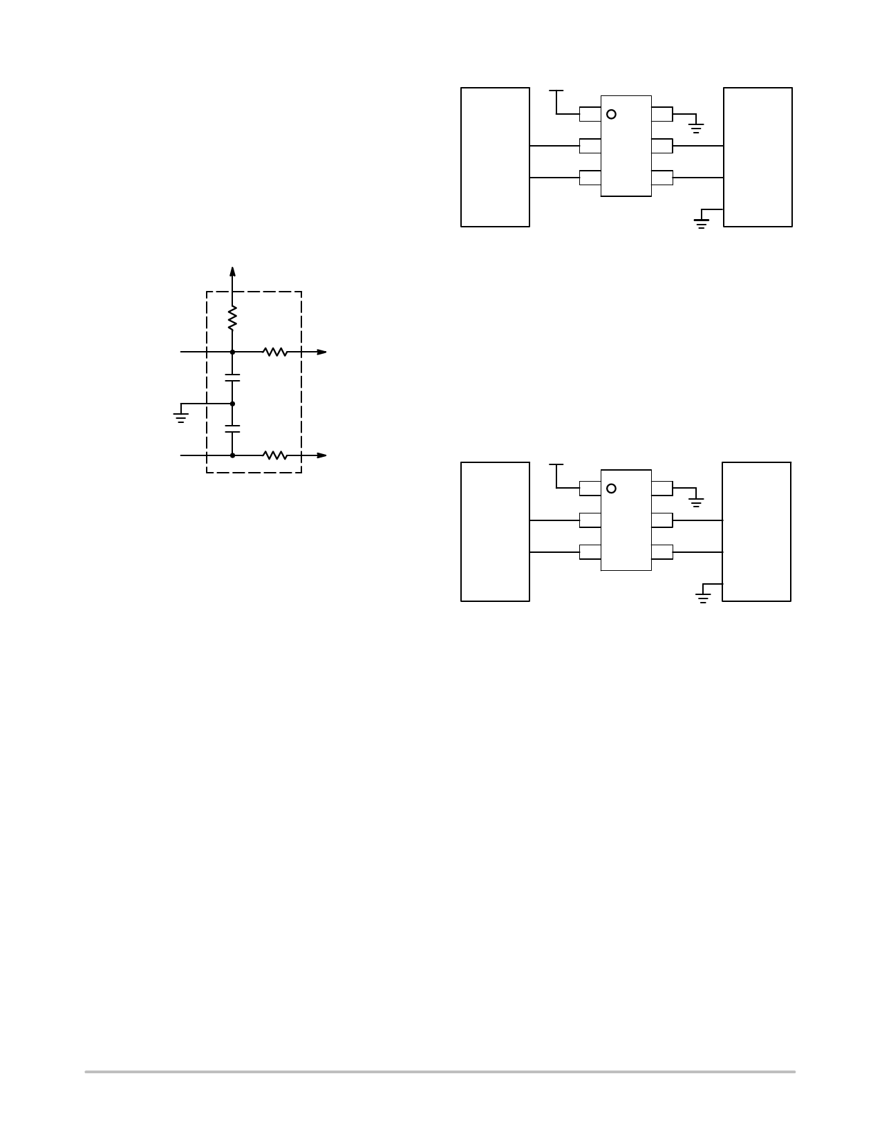
device). In the case of the STF202 device, it provides
upstream termination. The Figure 7 represents the
termination for an upstream USB port.
VCC
Rpu
RS
C
C
RS
Figure 7.
The USB Line termination is reached through the series
resistors placed in the D+ and D− lines. These resistors
insure the proper termination to maintain the integrity of the
signal. The Pull up Resistor of 1.5 kW on either the D+ or D−
data lines is used to identify the equipment as either
full−speed or low−speed device.
Connection for Full−Speed
and Low−Speed Devices
As mentioned before, there are two kinds of port devices:
Full−Speed devices − operates in 12 Mb/s
Low−Speed devices that work in 1.5 Mb/s
The STF202 device can be shaped to be used for either
Full−Speed or Low−Speed devices which is achieved as
described below:
Full−Speed Devices
The Pull up resistor (Rpu) is connected to the D+ Line.
The terminal 1 is connected to the Voltage Supply Line
(VBUS) while the terminal 6 is connected to ground. The
input of the D+ line is connected in the terminal 3 which
outputs from the terminal 4. Finally, the input of the D− line
is connected in the terminal 2 which outputs from the
terminal 5. The Figure 8 shows the connections of the
STF202 device for “Full−Speed devices”.
Peripheral
D−
D+
5V
1
6
2 STF202 5
3
4
USB
Controller
D−
D+
GND
Figure 8.
Low−Speed Devices
The Pull up resistor (Rpu) is connected to the D− Line. The
terminal 1 is connected to the Voltage Supply Line (VBUS)
while the terminal 6 is connected to ground. The input of the
D− line is connected in the terminal 3 which outputs from the
terminal 4. Finally, the input of the D+ line is connected in
the terminal 2 which outputs from the terminal 5. The Figure
9 shows the connections of the STF202 device for
“Low−Speed devices”.
5V
Peripheral
USB
1
6
Controller
D+
2 STF202 5
D+
D−
3
4
D−
GND
Figure 9.
http://onsemi.com
4
Share Link: 