HT48R30A-1 Просмотр технического описания (PDF) - Holtek Semiconductor
Номер в каталоге
Компоненты Описание
производитель
HT48R30A-1 Datasheet PDF : 39 Pages
| |||
HT48R30A-1/HT48C30-1
Bit No.
0
1
2
3
4
5
6
7
Label
EMI
EEI
ETI
¾
EIF
TF
¾
¾
Function
Controls the master (global) interrupt (1= enabled; 0= disabled)
Controls the external interrupt (1= enabled; 0= disabled)
Controls the Timer/Event Counter 0 interrupt (1= enabled; 0= disabled)
Unused bit, read as ²0²
External interrupt request flag (1= active; 0= inactive)
Internal Timer/Event Counter 0 request flag (1= active; 0= inactive)
Unused bit, read as ²0²
Unused bit, read as ²0²
INTC (0BH) Register
Interrupts, occurring in the interval between the rising
edges of two consecutive T2 pulses, will be serviced on
the latter of the two T2 pulses, if the corresponding inter-
rupts are enabled. In the case of simultaneous requests
the following table shows the priority that is applied.
These can be masked by resetting the EMI bit.
No.
Interrupt Source
Priority Vector
a External Interrupt
1
04H
b Timer/Event Counter Overflow 2
08H
The timer/event counter interrupt request flag (TF), ex-
ternal interrupt request flag (EIF), enable timer/event
counter interrupt bit (ETI), enable external interrupt bit
(EEI) and enable master interrupt bit (EMI) constitute an
interrupt control register (INTC) which is located at 0BH
in the data memory. EMI, EEI, ETI are used to control
the enabling/disabling of interrupts. These bits prevent
the requested interrupt from being serviced. Once the
interrupt request flags (TF, EIF) are set, they will remain
in the INTC register until the interrupts are serviced or
cleared by a software instruction.
It is recommended that a program does not use the
²CALL subroutine² within the interrupt subroutine. In-
terrupts often occur in an unpredictable manner or
need to be serviced immediately in some applications.
If only one stack is left and enabling the interrupt is not
well controlled, the original control sequence will be dam-
aged once the ²CALL² operates in the interrupt subrou-
tine.
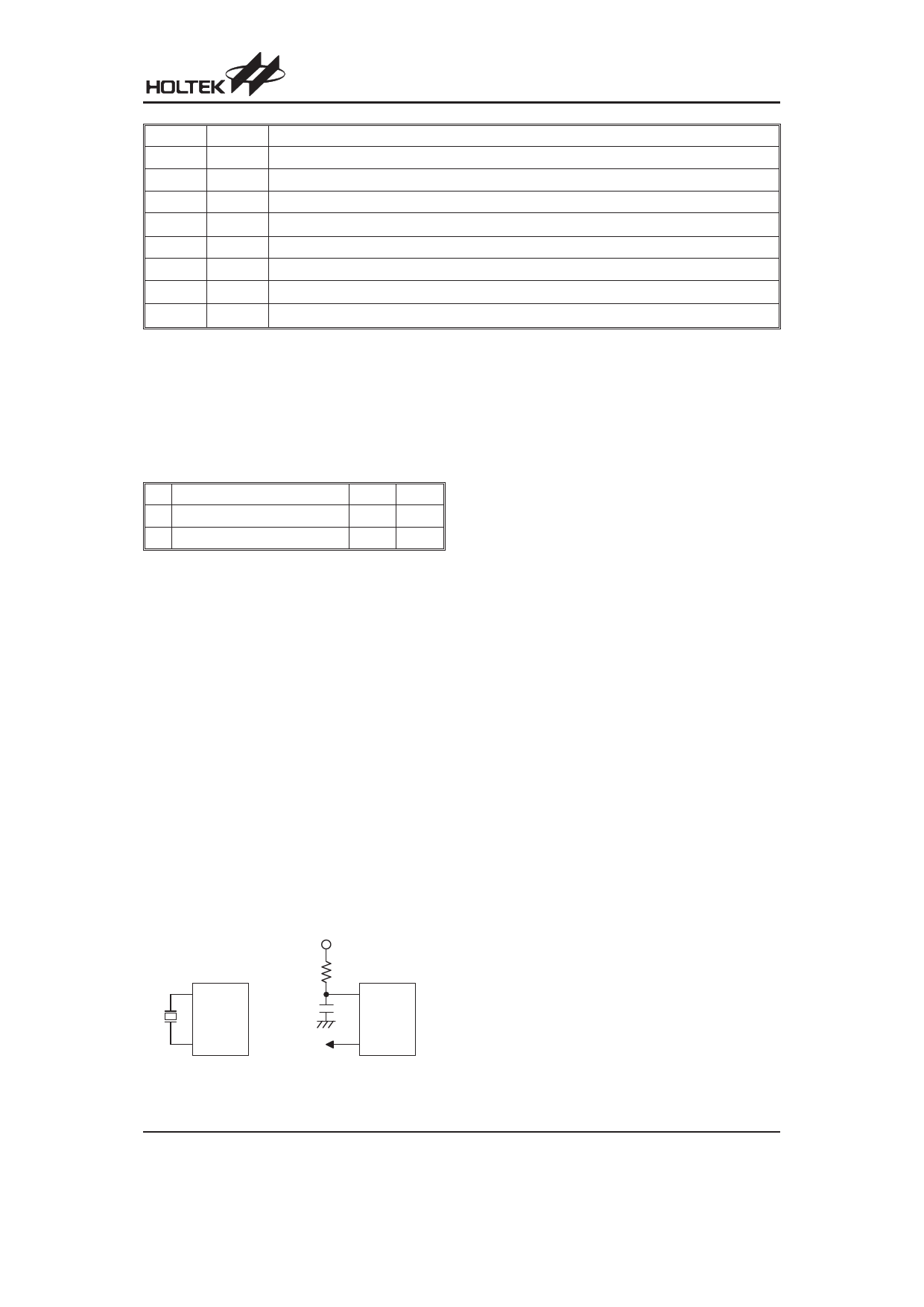
Oscillator Configuration
There are 3 oscillator circuits in the microcontroller.
V DD
O SC1
470pF
O SC1
O SC2
fS Y S /4
O SC2
N M O S O p e n D r a in
C r y s ta l O s c illa to r
R C O s c illa to r
( In c lu d e 3 2 7 6 8 H z )
System Oscillator
All of them are designed for system clocks, namely the
external RC oscillator, the external Crystal oscillator and
the internal RC oscillator, which are determined by op-
tions. No matter what oscillator type is selected, the sig-
nal provides the system clock. The HALT mode stops
the system oscillator and ignores an external signal to
conserve power.
If an RC oscillator is used, an external resistor between
OSC1 and VDD is required and the resistance must
range from 24kW to 1MW. The system clock, divided by
4, is available on OSC2, which can be used to synchro-
nize external logic. The RC oscillator provides the most
cost effective solution. However, the frequency of oscil-
lation may vary with VDD, temperatures and the chip it-
self due to process variations. It is, therefore, not
suitable for timing sensitive operations where an accu-
rate oscillator frequency is desired.
If the Crystal oscillator is used, a crystal across OSC1
and OSC2 is needed to provide the feedback and phase
shift required for the oscillator. No other external compo-
nents are required. In stead of a crystal, a resonator can
also be connected between OSC1 and OSC2 to get a
frequency reference, but two external capacitors in
OSC1 and OSC2 are required. If the internal RC oscilla-
tor is used, the OSC1 and OSC2 can be selected as
general I/O lines or an 32768Hz crystal oscillator (RTC
OSC). Also, the frequencies of the internal RC oscillator
can be 3.2MHz, 1.6MHz, 800kHz and 400kHz (depends
on the options).
The WDT oscillator is a free running on-chip RC oscilla-
tor, and no external components are required. Even if
the system enters the power down mode, the system
clock is stopped, but the oscillator still works within a pe-
riod of 65ms at 5V. The WDT oscillator can be disabled
by options to conserve power.
Rev. 2.00
10
April 24, 2009
Share Link: 