LC6514B Просмотр технического описания (PDF) - SANYO -> Panasonic
Номер в каталоге
Компоненты Описание
производитель
LC6514B
SANYO -> Panasonic

LC6514B Datasheet PDF : 17 Pages
| |||
LC6514B
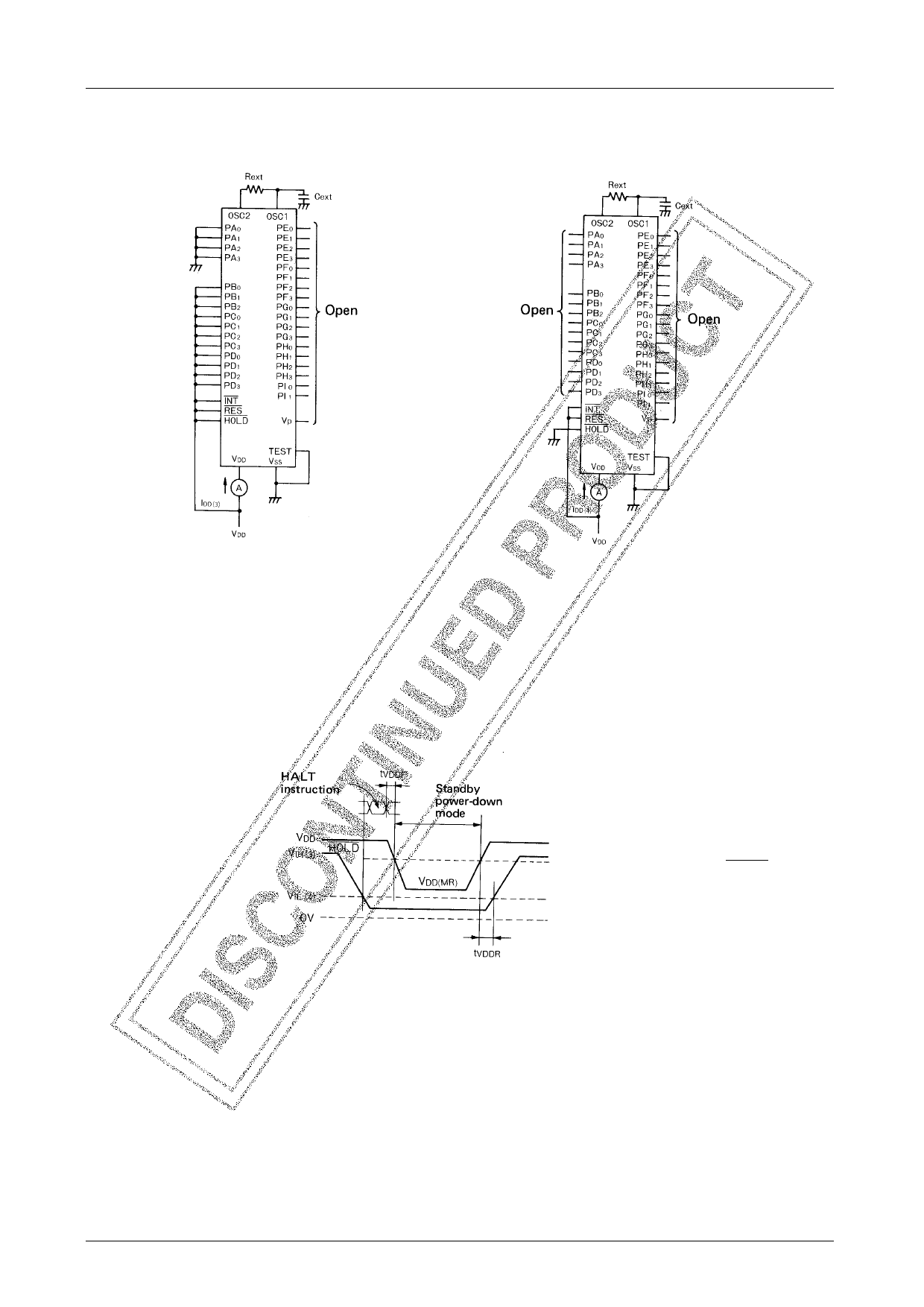
Fig. 4 IDD3 Test Circuit
Input/output common
port C, D : Output inhibit
The HALT instruction is
executed to csuse the
HALT mode to be
entered.
Fig. 5 IDD4 Test Circuit
(Note)
During the HALT instruction
execution cycle, no chattering
must be applied to the HOLD
pin and PA0 to 3 pins.
Fig. 6 Standby Mode Timing
No.1802–7/17
Share Link: