DS7505(2015) Просмотр технического описания (PDF) - Maxim Integrated
Номер в каталоге
Компоненты Описание
производитель
DS7505 Datasheet PDF : 14 Pages
| |||
DS7505
Digital Thermometer and Thermostat
Slave Address: Every slave device on the bus has a
unique 7-bit address that allows the master to access that
device. The DS7505’s 7-bit bus address is 1 0 0 1 A2 A1
A0, where A2, A1, and A0 are user-selectable through the
corresponding input pins. The three address pins allow up
to eight DS7505s to be multidropped on the same bus.
Address Byte: The control byte is transmitted by the
master and consists of the 7-bit slave address plus a
read/write (R/W) bit (see Figure 7). If the master is going
to read data from the slave device then R/W = 1, and if
the master is going to write data to the slave device then
R/W = 0.
Pointer Byte: The pointer byte is used by the master to
tell the DS7505 which register is going to be accessed
during communication. The six MSBs of the pointer byte
(see Figure 8) are always 0 and the two LSBs correspond
to the desired register as shown in Figure 8.
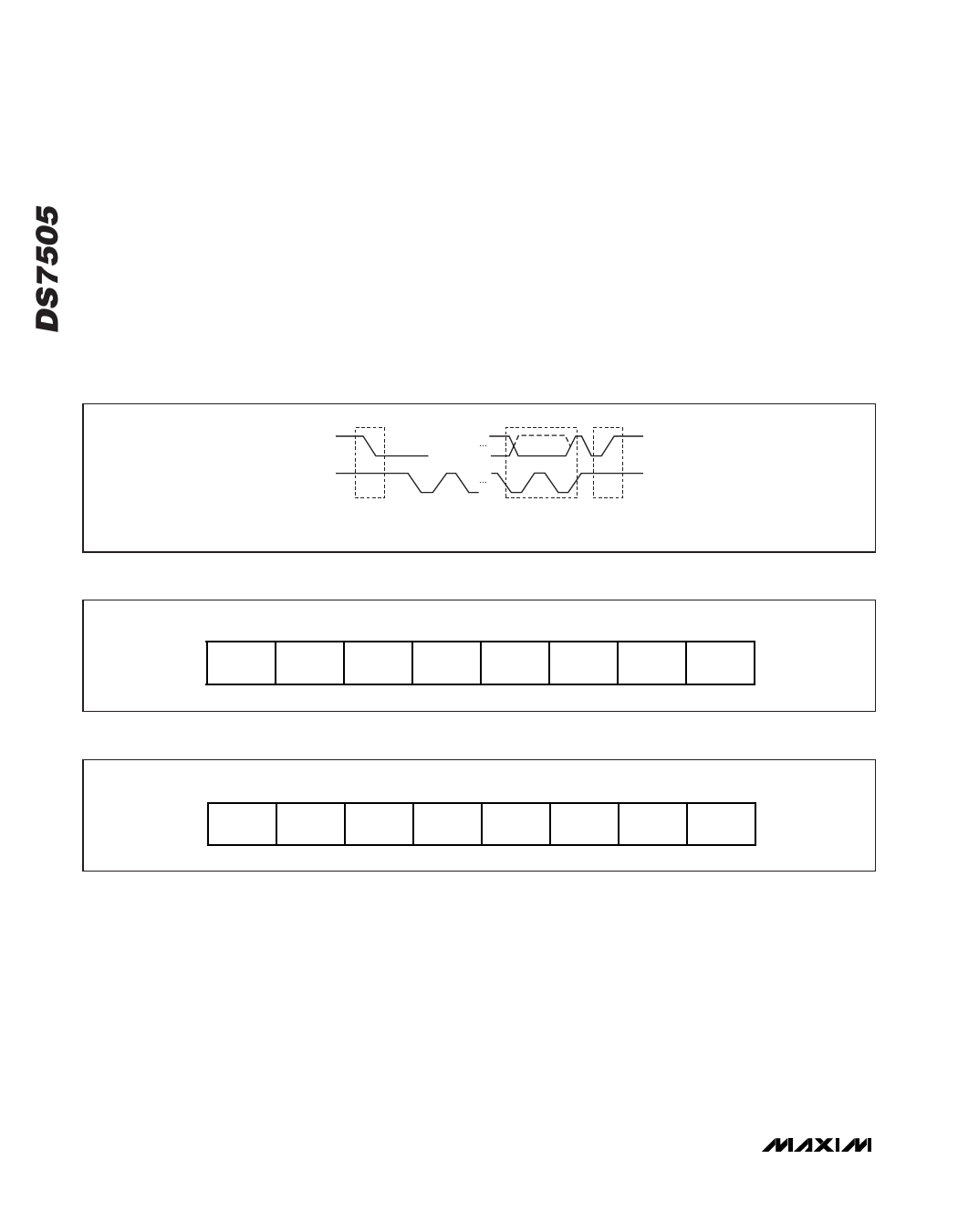
SDA
SCL
START
CONDITION
Figure 6. Start, Stop, and ACK Signals
ACK (OR NACK) STOP
FROM RECEIVER CONDITION
Bit 7
1
Bit 6
0
Bit 5
0
Bit 4
1
Bit 3
A2
Bit 2
A1
Bit 1
A0
Bit 0
R/W
Figure 7. Address Byte
Bit 7
0
Bit 6
0
Bit 5
0
Bit 4
0
Bit 3
0
Bit 2
0
Bit 1
P1
Bit 0
P0
Figure 8. Pointer Byte
www.maximintegrated.com
Maxim Integrated │ 10
Share Link: 