ADM1191-2ARMZ-R71(RevB) Просмотр технического описания (PDF) - Analog Devices
Номер в каталоге
Компоненты Описание
производитель
ADM1191-2ARMZ-R71 Datasheet PDF : 16 Pages
| |||
Digital Power Monitor
with Convert Pin and ALERTB Output
ADM1191
FEATURES
Powered from 3.15 V to 26 V
Precision current sense amplifier
Precision voltage input
12-bit ADC for current and voltage readback
Convert (CONV) pin for commanding an ADC read
SETV input for setting overcurrent alert threshold
ALERTB output provides an overcurrent interrupt
I2C fast mode-compliant interface (400 kHz maximum)
2 address pins allow 16 devices on the same bus
10-lead MSOP
APPLICATIONS
Power monitoring/power budgeting
Central office equipment
Telecommunications and data communications equipment
PCs/servers
GENERAL DESCRIPTION
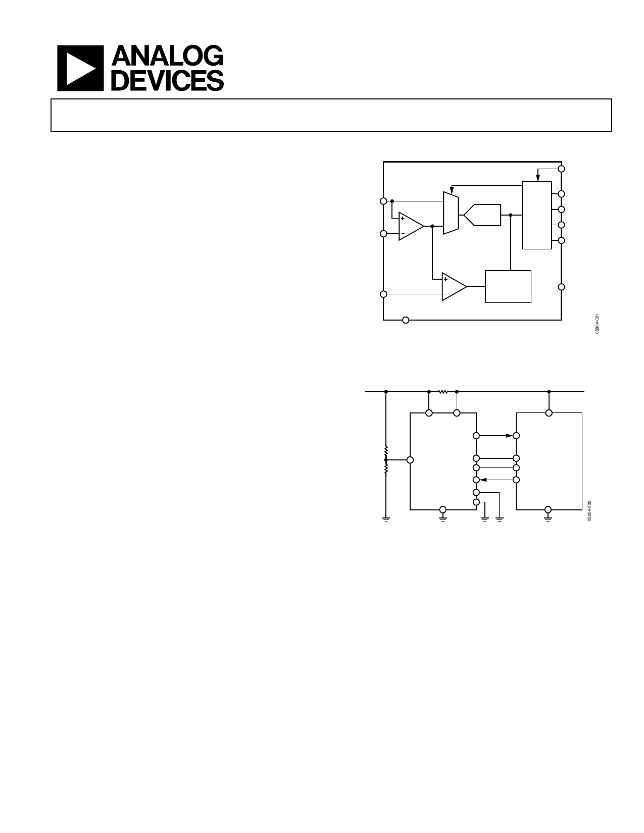
The ADM1191 is an integrated current sense amplifier that
offers digital current and voltage monitoring via an on-chip
12-bit analog-to-digital converter (ADC), communicated
through an I2C® interface.
An internal current sense amplifier measures voltage across the
sense resistor in the power path via the VCC pin and the SENSE pin.
A 12-bit ADC can measure the current seen in the sense
resistor, as well as the supply voltage on the VCC pin.
An industry-standard I2C interface allows a controller to read
current and voltage data from the ADC. Measurements can be
initiated by an I2C command or via the convert (CONV) pin.
The CONV pin is especially useful for synchronizing reads on
multiple ADM1191 devices. Alternatively, the ADC can run
continuously, and the user can read the latest conversion data
whenever it is required. Up to 16 unique I2C addresses can be
created, depending on the way the A0 pin and the A1 pin are
connected.
A SETV pin is also included. A voltage applied to this pin is
internally compared with the output voltage on the current
sense amplifier. The output of the SETV comparator asserts
when the current sense amplifier output exceeds the SETV
voltage. When this event occurs, the ALERTB output asserts.
FUNCTIONAL BLOCK DIAGRAM
ADM1191
CONV
VCC
V
0
SENSE
A
CURRENT
SENSE
AMPLIFIER
I
1
MUX
12-BIT
ADC
SDA
I2C
SCL
A1
A0
SETV
COMPARATOR
ALERT
GND
Figure 1.
ALERTB
3.15V TO 26V
RSENSE
VCC SENSE
ALERTB
ADM1191
SETV
SDA
SCL
CONV
A1
GND A0
CONTROLLER
INTERRUPT
P = VI
SDA
SCL
CONV
Figure 2. Applications Diagram
The ALERTB output can be used as a flag to warn a micro-
controller or field programmable gate array (FPGA) of an
overcurrent condition. ALERTB outputs of multiple ADM1191
devices can be tied together and used as a combined alert.
The ADM1191 is packaged in a 10-lead MSOP.
Rev. B
Information furnished by Analog Devices is believed to be accurate and reliable. However, no
responsibility is assumed by Analog Devices for its use, nor for any infringements of patents or other
rights of third parties that may result from its use. Specifications subject to change without notice. No
license is granted by implication or otherwise under any patent or patent rights of Analog Devices.
Trademarks and registered trademarks are the property of their respective owners.
One Technology Way, P.O. Box 9106, Norwood, MA 02062-9106, U.S.A.
Tel: 781.329.4700
www.analog.com
Fax: 781.461.3113 ©2006–2008 Analog Devices, Inc. All rights reserved.
Share Link: 