MAX9205(2001) Просмотр технического описания (PDF) - Maxim Integrated
Номер в каталоге
Компоненты Описание
производитель
MAX9205 Datasheet PDF : 13 Pages
| |||
10-Bit Bus LVDS Serializers
Initialization Mode
When VCC is applied, the outputs are held in high
impedance and internal circuitry is disabled by on-chip
power-on-reset circuitry. When VCC reaches 2.35V, the
PLL starts to lock to a local reference clock (16MHz to
40MHz for MAX9205 and 40MHz to 66MHz for
MAX9207). The reference clock, TCLK, is provided by
the system. A serializer locks within 2049 cycles of
TCLK. Once locked, a serializer is ready to send data
or SYNC patterns depending on the levels of SYNC 1
and SYNC 2.
Synchronization Mode
To rapidly synchronize with a deserializer, SYNC pat-
terns can be sent. A SYNC pattern is six consecutive
ones followed by six consecutive zeros repeating every
TCLK period. When one or both SYNC inputs are
asserted high for at least six cycles of TCLK, the serial-
izer will initiate the transmission of 1024 SYNC patterns.
The serializer will continue to send SYNC patterns if
either of the SYNC input pins remains high. Toggling
one SYNC input with the other SYNC input low before
1024 SYNC patterns are output does not interrupt the
output of the 1024 SYNC patterns.
Data Transmission Mode
After initialization, both SYNC input pins must be set
low by users or through a control signal from the dese-
rializer before data transmission begins. Provided that
SYNC inputs are low, input data at IN0–9 are clocked
into the serializer by the TCLK input. Setting TCLK_R/F
high selects the rising edge of TCLK for data strobe
and low selects the falling edge. If either of the SYNC
inputs goes high for six TCLK cycles at any time during
data transmission, the data at IN0–9 are ignored and
SYNC patterns are sent for at least 1024 TCLK cycles.
A start bit high and a stop bit low frame the 10-bit data
and function as the embedded clock edge in the serial
data stream. The serial rate is the TCLK frequency
times the data and appended bits. For example, if
TCLK is 40MHz, the serial rate is 40 x 12 (10 + 2 bits) =
480Mbps. Since only 10 bits are from input data, the
payload rate is 40 x 10 = 400Mbps.
Power-Down
Power-down mode is entered when the PWRDN pin is
driven low. In power-down mode, the PLL of the serial-
izer is stopped and the outputs (OUT+ and OUT-) are
in high impedance, disabling drive current and also
reducing supply current. When PWRDN is driven high,
the serializer must reinitialize and resynchronize before
data can be transferred.
High-Impedance State
The serializer output pins (OUT+ and OUT-) are held in
high impedance when VCC is first applied and while the
PLL is locking to the local reference clock. Setting EN
or PWRDN low puts the device in high impedance.
After initialization, EN functions asynchronously. For
example, the serializer output can be put into high
impedance while SYNC patterns are being sent without
affecting the internal timing of the SYNC pattern gener-
ation. However, if the serializer goes into high imped-
ance, a deserializer loses PLL lock and needs to
resynchronize before data transfer can resume.
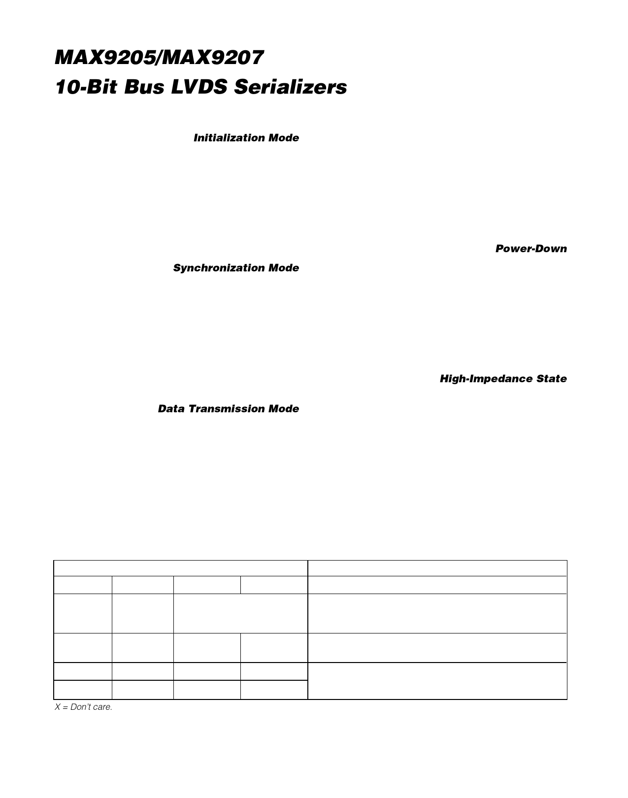
Table 1. Input /Output Function Table
INPUTS
EN
PWRDN
SYNC 1
SYNC 2
When either or both SYNC 1
H
H
and SYNC 2 are held high for
at least six TCLK cycles
H
H
L
L
X
L
X
X
L
X
X
X
X = Don’t care
OUTPUTS
OUT+, OUT-
Synchronization Mode. SYNC patterns of six 1s and six 0s are
transmitted every TCLK cycle for at least 1024 TCLK cycles.
Data at IN0–9 are ignored.
Data Transmission Mode. IN0–9 and 2 frame bits are
transmitted every TCLK cycle.
Output in high-impedance.
6 _______________________________________________________________________________________
Share Link: 