VV0670P001 Просмотр технического описания (PDF) - Vision
Номер в каталоге
Компоненты Описание
производитель
VV0670P001 Datasheet PDF : 36 Pages
| |||
Colour Processor Interface ASIC
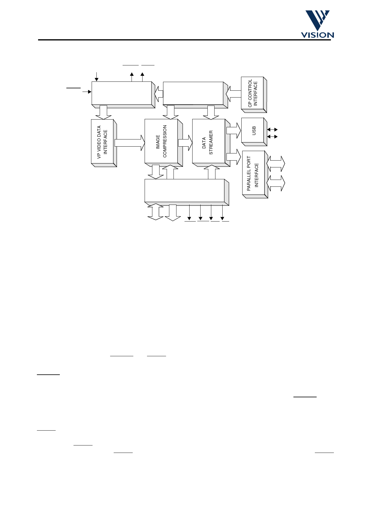
2.2 Video Compressor Module
CLK400H
LOWPO NORM
RESET
POWER
MANAGEMENT
REGISTERS
D+
D-
DRAM
CONTROLLER
RAMA[8:0] RAMD[15:0] LCAS UCAS RAS WE
Block Diagram of CPiA Video Compressor Module
2.2.1 Power Management
The power management block is primarily responsible for low-level control of system power, clocks and reset
sequences to ensure full compliance with the USB specification and power saving modes of operation. This
module also includes a watchdog reset ensuring, for example, the system always returns to a safe state if
power-failure or any other event has caused CPiA to encounter an unknown and fatal error.
CPiA requires up to 3 independent power supplies. When CPiA is designed into a product providing full USB
power consumption compliance, the system must provide CPiA with VDD=5V, a switched VDDA=5V and
VDDU=3.3V (for internal USB differential pads). If CPiA is used in a target application where only the parallel
port interface is required and slightly higher module power consumption is permitted, a single, constant 5V
supply can be safely fed to VDD, VDDA and VDDU.
VDD and VDDU must always be permanently connected to system power supplies. The switched VDDA
power line is typically supplied using a power FET external to CPiA. The power management module
provides two outputs for driving the FET gates and hence is capable of enabling or disabling power to
system-level components; LOPOW and NORM.
LOPOW is asserted when CPiA is ready for VDDA to be powered and once power has been applied puts
CPiA into a state where commands received from the host PC can be processed. As well as VDDA becoming
active, this also includes starting up of high-speed 14.318MHz and 48MHz clocks using external crystals,
resetting and initialising all internal state machines and logic within VP, VC and CP modules. LOPOW is de-
asserted at any time the host PC requests the module is either put into a USB SUSPEND condition or any
other host-application-dependent mode when ultra low power consumption is required.
NORM is asserted when CPiA is ready to put the module into the highest power mode of operation which
occurs when the camera becomes active and high speed image transfers via USB or parallel port interfaces
commences. NORM is used internally to CPiA only but is provided as an optional output for driving customer-
specific logic. For example, NORM can be used to illuminate an LED indicating the camera is active. NORM
is also deasserted at any time the host requests USB SUSPEND mode.
V:\apps\cpia\docs\cpia datasheet\cpia_datasheet4.fm
02/07/98
10
Commercial In Confidence
Share Link: 