UT1750AR12WCC Просмотр технического описания (PDF) - Aeroflex UTMC
Номер в каталоге
Компоненты Описание
производитель
UT1750AR12WCC Datasheet PDF : 56 Pages
| |||
UART Receiver Register (RCVR)
The UART Receiver Buffer Register (see figure 9) receives
9600-baud asynchronous serial data through the UARTIN input
pin on the UT1750AR. Each serial data string contains an active-
low Start bit, eight Data bits, an odd Parity bit, and an active-
high Stop bit. Figure 10 shows a single serial data string.
15 14 13 12 11 10 9
0 000000
876 54 3210
RR RRRRRR
CC CCCCCC
DD DDDDDD
076 543210
MSB
LSB
Figure 9. The UART Receiver
UART Transmitter Buffer Register (TXMT)
The UT1750AR’s internal UART forms an 11-bit serial data
string by combining a Start bit, the eight Data bits from the
Transmitter Buffer Register (TXMT), an odd Parity bit, and a
Stop bit. Figure 11 shows the composition of the serial data
string.
The UT1750AR transmits this serial data string through the
UARTOUT pin at a rate of 9600 baud.
DIRECTION
OF DATA
FLOW OUT
OF THE
UT1750AR
S T TTT TTTT
T X X XX X X XX
R D D D D DD D D
T 0 123 45 67
S
PT
AO
RP
Figure 11. UART Transmitter Data String
DATA
FLOW
S R RRR RRRR
S
T C C CC C C CC P T
R D D D D DD D D AO
T 0 1 2 3 4 5 6 7 RP
Figure 10. UART Receiver Data String
While receiving a serial data string, the UT1750AR generates
four status flags: Data Ready (DR); Overrun Error (OE);
Framing Error (FE); and Parity Error (PE). The UT1750AR
stores these status bits in the System Status Register (STATUS).
Receiver buffer register bits 15-8 are always low. Bit numbers
7-0 (RCD7-RCD0) contain data the UT1750AR receives via the
serial data port. RCD7 is the MSB; RCD0 is the LSB.
Two status signals are associated with transmitting serial data.
These signals are the UART Transmitter Buffer Empty (TBE)
and UART Transmitter Register Empty (TE). TBE and TE are
both active high and provide information on the status of double
buffering the UART’s transmitted data. TBE and TE are read
from the System Status Register as bits 2 and 1, respectively.
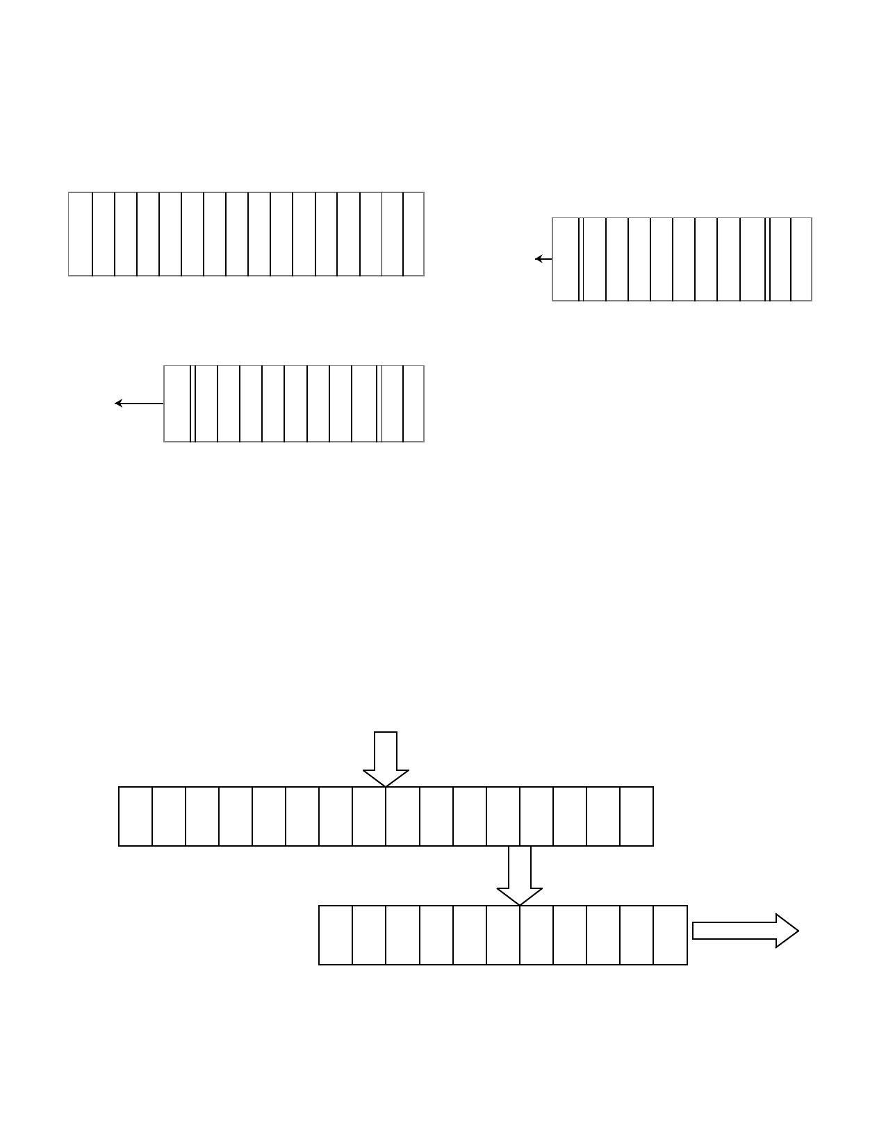
The UT1750AR’s internal UART has a double-buffered data
transmission scheme (figure 12). The UT1750AR first loads the
data for transmission into the Transmitter Buffer Register. If the
UART Transmitter Register is empty, data from the TXMT
automatically transfers to the UART Transmitter Register. At
this time, the TBE bit goes active indicating more data may be
loaded into the TXMT. This double-buffering scheme allows
contiguous transmission of serial data streams and also
decreases the UT1750AR’s required overhead for the UART
interface.
THE UT1750AR’S INTERNAL
DATA BUS
UART TRANSMITTER BUFFER
REGISTER (TBR)
16
STATUS OF THE
D
C
D
C
D
C
D
C
D
C
D
C
D
C
D
C
T
X
D
T
X
D
T
X
D
T
X
D
T
X
D
T
X
D
T
X
D
T
X
D
TBR IS READ
FROM BIT 2
OF THE SYSTEM
7 6 5 4 3 2 1 0 STATUS REGISTER
DATA IS LOADED INTO THE
TBR WITH AN OUTPUT
REGISTER (OTR) INSTRUCTION
STATUS OF THE UART
TRANSMITTER REGISTER IS
READ FROM BIT 1
OF THE SYSTEM STATUS
REGISTER
UART TRANSMITTER
REGISTER
8
SPT T T T T T T T S
T AXXXXXXXXT
OR7 6 5 4 3 2 1 0 R
P
T
DIRECTION OF
DATA FLOW
Figure 12. The UT1750AR UART Double-Buffered Transmitter Register
16
Share Link: 