MM1292KF Просмотр технического описания (PDF) - Mitsumi
Номер в каталоге
Компоненты Описание
производитель
MM1292KF Datasheet PDF : 7 Pages
| |||
MITSUMI
Protection of Lithium Ion Batteries (two cells in series) MM1292
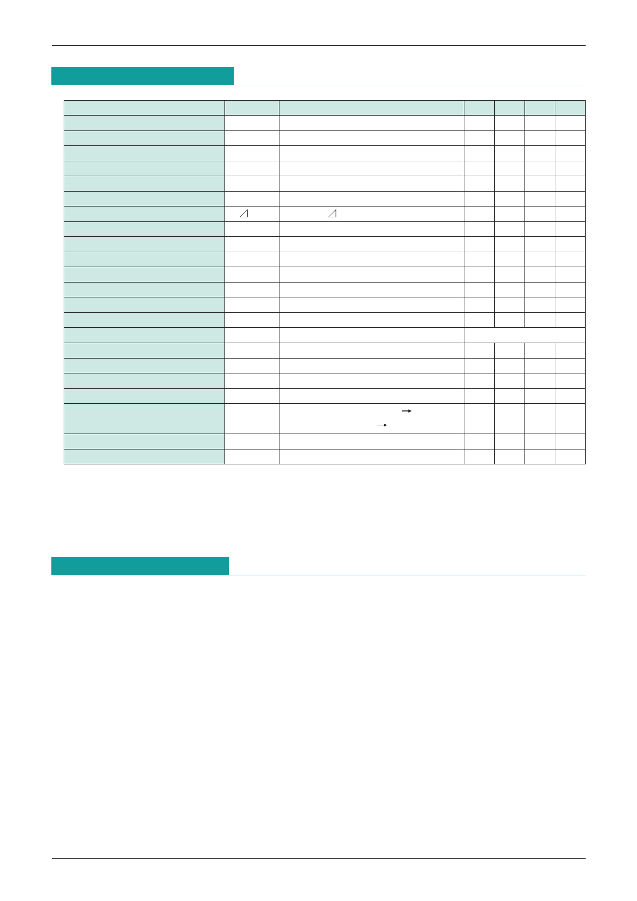
Electrical Characteristics (unless otherwise specified, Ta=25°C)
Item
Current consumption 1
Current consumption 2
Current consumption 3
Current consumption 4
VL pin input voltage
Overcurrent detection voltage
Hysteresis voltage
Overcharge detection voltage
Discharge resumption voltage
Starting voltage
GD pin output voltage H
GD pin output voltage L
OC pin output current
Overcurrent detection voltage
Reset by overcurrent
Overcurrent detection delay 1
Overcurrent detection delay 2
Excess discharge detection delay
TC pin charge current
Symbol
IVH1
IVH2
IVH3
IVH4
IVL
VALM
VAL
VS
VDF
VST
VGDH
VGDL
IOCH
VCS
TOC1
TOC2
TOD
ITC1
TC pin threshold value
VTC
Non-induction time for overcharge TOC
Operating limit voltage
VOPL
Measurement Conditions
Min. Typ. Max. Units
VCELL=4.5V, ROC=270kΩ
80 100 µA
VCELL=3.5V (normal)
13.0 20.0 µA
VCELL=1.9V (During excess discharge)
0.5 0.8 µA
VCELL=1.0V (During excess discharge)
0.1 µA
VH=VL
-0.3 0 0.3 µA
Ta=-20°C~70°C
4.20 4.25 4.30 V
VAL=VALMH-VALML
140 200 260 mV
2.30 2.40 2.50 V
Discharge resumed through voltage rise 2.90 3.00 3.10 V
Voltage applied between GND-CS pins -0.6 -0.5
V
VCELL=3.5V, IL=10µA
VH-0.3 VH-0.2
V
VCELL=3.5V, IL=10µA, VCS=1V
0.2 0.3 V
VCELL=4.5V
20 150
µA
135 150 165 mV
load release
10 20
mS
between CS-GND pins > 0.8V
30 100 µS
10 20
mS
30 50 80 nA
VCELL=4.5V, VTC=0 5V
VOC=L H
3.65 3.90 4.15 V
CTC=0.012µF
0.5 1.0 1.5 S
0.9 V
Note 1. For current consumption, it is assumed that high side cell voltage and low side cell voltage are
identical. When the cell voltages differ, it is set by the higher voltage.
2. GD pin are high impedance when the current consumption is below the operating limit voltage.
3. When the circuit configuration calls for discharge resumption through charging, the discharge
resumption voltage is 2.4V typ.
Description of Operation
[Outline]
This IC is used for protecting lithium ion batteries (two cell series connection type). Overcharge detection,
excess discharge detection, and overcurrent detection are built into each circuit. It controls the FET for
discharge control and charge control (external N-MOS FET). There are four major operating modes.
1. Overcharge mode
When the voltage between Vh-VI and VI-GND exceeds the overcharge voltage (VALM).
2. Normal mode
When the voltage between Vh-VI and VI-GND exceeds the excess discharge voltage (VS) and is less
than the over charge voltage (VALM).
3. Excess discharge mode
When the voltage between Vh-VI and VI-GND is less than the excess discharge voltage (VS).
4. Overcurrent mode
When the voltage between CS-GND is less than the overcurrent voltage (VCS).
Share Link: 