LT1319 Просмотр технического описания (PDF) - Linear Technology
Номер в каталоге
Компоненты Описание
производитель
LT1319 Datasheet PDF : 12 Pages
| |||
LT1319
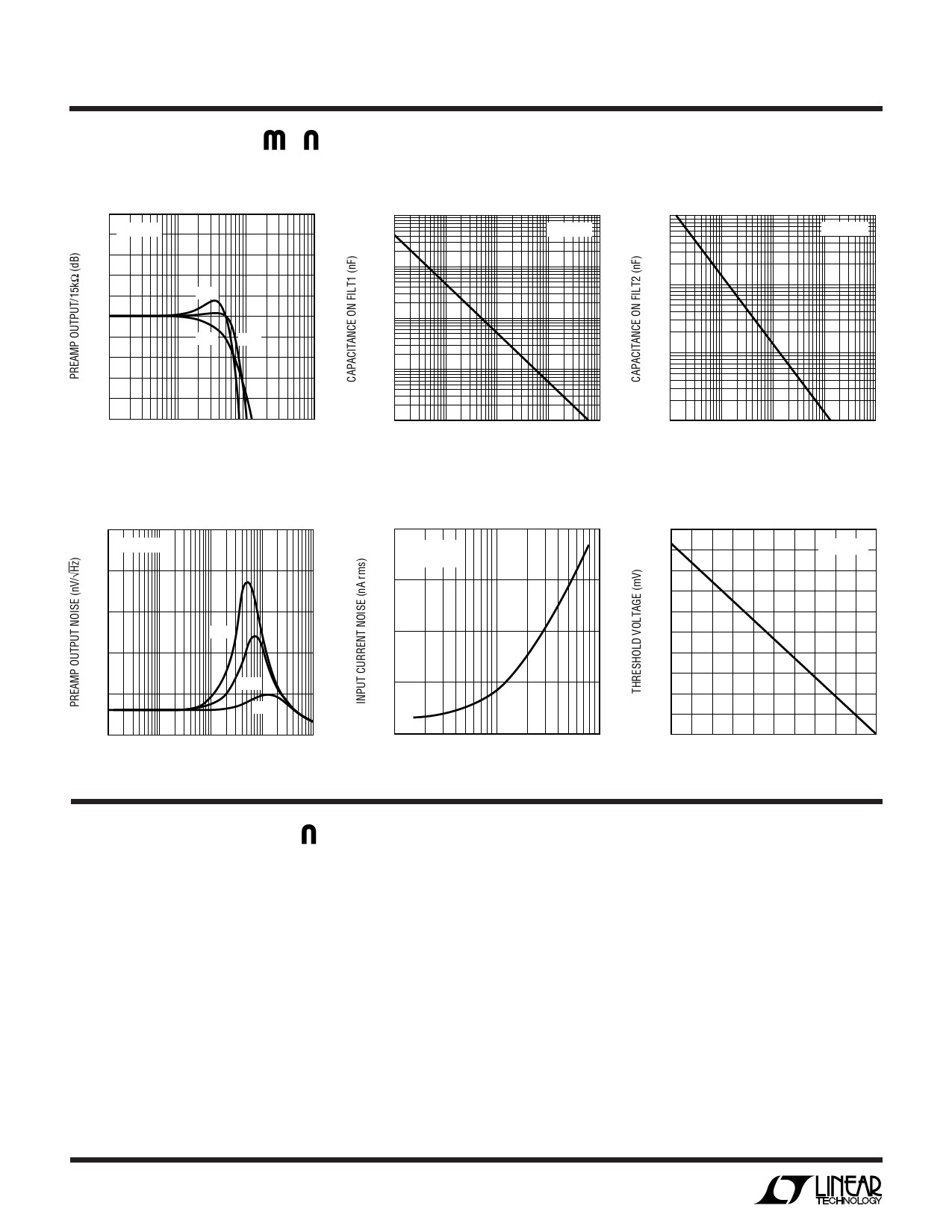
TYPICAL PERFORMANCE CHARACTERISTICS
Preamp Frequency Response vs
Input Capacitance
5
4 TA = 25°C
3
2
1
50pF
0
–1
10pF 30pF
–2
–3
–4
–5
100k
1M
10M
FREQUENCY (Hz)
100M
1319 G01
Preamp Highpass vs
Capacitance on FILT1
1000
TA = 25°C
100
10
1
Gain Stage Highpass vs
Capacitance on FILT2 or FILT2L
1000
TA = 25°C
100
10
0.1
100
1k
10k
100k
1M
HIGHPASS CORNER FREQUENCY (Hz)
1319 G02
1
1k
10k
100k
1M
10M
HIGHPASS CORNER FREQUENCY (Hz)
1319 G03
Preamp Output Noise vs
Input Capacitance
250
TA = 25°C
200
Input-Referred Noise vs
Lowpass Filter on PREOUT
20
TA = 25°C
RFILTER = 1k
15
FILTIN- or FILTINL- Referred
Threshold Voltage vs RT1
1.0
TA = 25°C
0.9
150
0.8
50pF
10
100
0.7
50
0
10k
30pF
10pF
100k
1M
10M
FREQUENCY (Hz)
100M
1319 G04
5
0
0.1
1
10
FILTER CUTOFF FREQUENCY (MHz)
1319 G05
0.6
0.5
20
30
RT1 (kΩ)
40
1319 G06
U
CIRCUIT DESCRIPTIO
The LT1319 is a general purpose low noise, high speed,
high gain, infrared receiver designed to easily provide IR
communications with portable computers, PDAs, desktop
computers and peripherals. The receiver takes the photo-
current from an infrared photodiode (Siemens BPW34FA
or Temic BPV22NF) and performs a current-to-voltage
conversion. After external filtering that is tailored for the
desired communication standard, two filter buffers are
provided. There are dual gain chains with nominal gain of
400V/V that feed internal comparators with hysteresis. The
comparator thresholds are set externally with a current into
the VTH pin. The high frequency comparator has a response
time of 25ns and is well-suited to high data rates.
4
The low frequency comparator responds in 60ns and is
useful for more modest data rates such as Sharp/Newton
and IRDA-SIR. The circuit also contains shutdown circuitry
to reduce power consumption. Rejection of ambient inter-
ference is accomplished with AC coupling loops around the
preamp and the two gain stages. The rejection frequency is
set with an internal resistor and an external capacitor to
ground. This feature allows changing of the break fre-
quency by simply switching in additional capacitors. To aid
in rejection of power supply noise there is internal supply
regulation and a fully differential topology after the filter
buffers.
1319fb
Share Link: 