DS1991 Просмотр технического описания (PDF) - Dallas Semiconductor -> Maxim Integrated
Номер в каталоге
Компоненты Описание
производитель
DS1991 Datasheet PDF : 14 Pages
| |||
DS1991
1-WIRE SIGNALING
The DS1991 requires strict protocols to ensure data integrity. The protocol consists of four types of
signaling on one line: Reset Sequence with Reset Pulse and Presence Pulse, Write 0, Write 1 and Read
Data. All these signals except presence pulse are initiated by the bus master. The initialization sequence
required to begin any communication with the DS1991 is shown in Figure 10. A reset pulse followed by a
presence pulse indicates the DS1991 is ready to send or receive data given the correct ROM command
and memory function command. The bus master transmits (TX) a reset pulse (tRSTL, minimum 480 µs).
The bus master then releases the line and goes into receive mode (RX). The 1-Wire bus is pulled to a high
state via the pullup resistor. After detecting the rising edge on the data pin, the DS1991 waits (tPDH, 15-60
µs) and then transmits the presence pulse (tPDL, 60-240 µs).
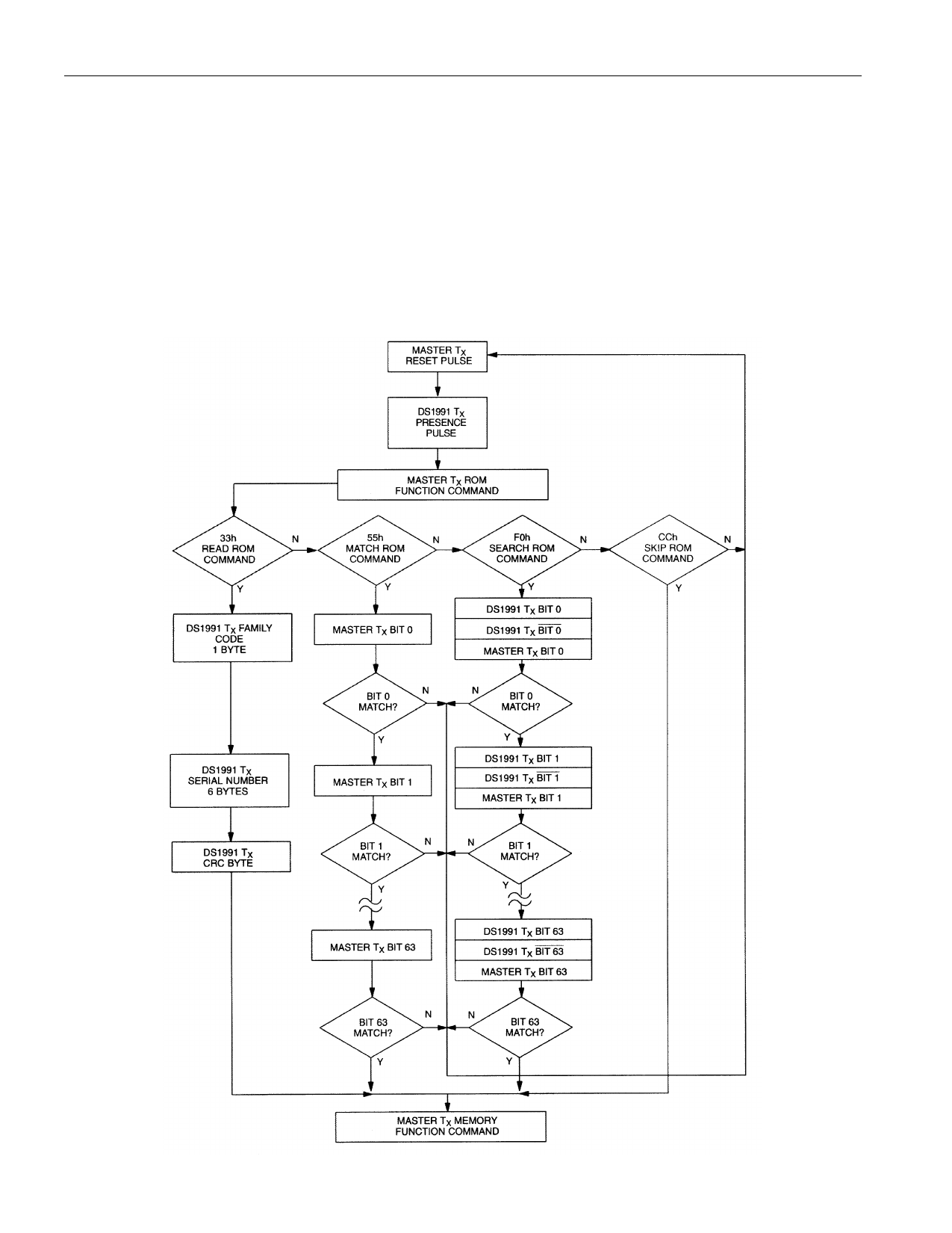
ROM FUNCTIONS FLOW CHART Figure 9
10 of 14
Share Link: 