CMX969E2 Просмотр технического описания (PDF) - MX-COM Inc
Номер в каталоге
Компоненты Описание
производитель
CMX969E2 Datasheet PDF : 35 Pages
| |||
MOTIENTSM/ARDISSM RD-LAPTM MDC4800 Modem
7
4 General Description
CMX969 Advance Information
4.1 Description of Blocks
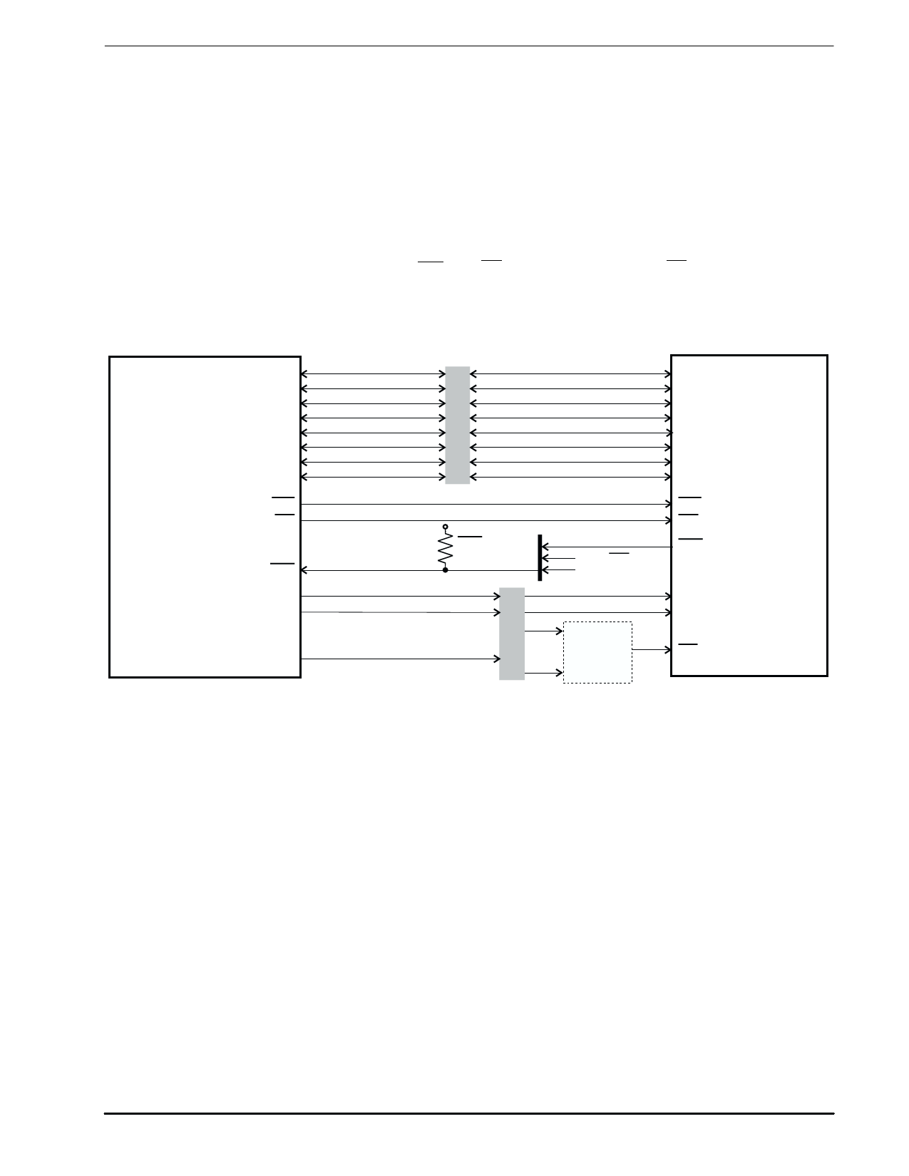
Refer to Figure 1.
4.1.1 Data Bus Buffers
Eight bi-directional 3-state logic level buffers between the modem's internal registers and the host µC's data
bus lines.
4.1.2 Address and R/W Decode
This block controls the transfer of data bytes between the µC and the modem's internal registers, according to
the state of the Write and Read Enable inputs ( WR and RD ), the Chip Select input ( CS ) and the Register
Address inputs A0 and A1.
The Data Bus Buffers, Address and R/W Decode blocks provide a byte-wide parallel µC interface, which can
be memory-mapped, as shown in Figure 3.
D0
D1
D2
D3
D4
D5
D6
D7
µCONTROLLER
WR
RD
IRQ
A0
A.....1
An
µC Data Bus
VDD
IRQ pull up
resistor
.....
.....
µC Address Bus
D0
D1
D2
D3
D4
D5
D6
D7
WR
RD
IRQ
other IRQ inputs
to µController
A0
A1
Modem
Address
CS
Decode
MODEM
Figure 3: Typical Modem µC Connections
4.1.3 Status and Data Quality Registers
Two 8-bit registers which the µC can read to determine the status of the modem and the received data
quality.
4.1.4 Command, Mode and Control Registers
The values written by the µC to these 8-bit registers control the operation of the modem.
4.1.5 Data Buffer
A 12-byte buffer used to hold receive or transmit data to or from the µC.
4.1.6 CRC Generator/Checker
A circuit which generates (in transmit mode) or checks (in receive mode) the Cyclic Redundancy Checksum
bits, which are included in transmitted data blocks so that the receive modem can detect transmission errors.
4.1.7 FEC Encoder/Decoder
In transmit mode, this circuit adds Forward Error Correction information to the transmitted data. In RD-LAP
mode it also converts the binary data to 4-level symbols. In receive mode, this block translates received
symbols to binary data, using the FEC information to correct a large proportion of transmission errors.
¤2001 MX-COM, Inc.
www.mxcom.com Tel: 800 638 5577 336 744 5050 Fax: 336 744 5054
Doc. # 20480211.002
4800 Bethania Station Road, Winston-Salem, NC 27105-1201 USA All trademarks and service marks are held by their respective companies.
Share Link: 