MAX697EWE Просмотр технического описания (PDF) - Maxim Integrated
Номер в каталоге
Компоненты Описание
производитель
MAX697EWE Datasheet PDF : 16 Pages
| |||
MAX696/MAX697
Microprocessor Supervisory Circuits
low for 50ms after LLIN rises above 1.3V. This prevents
repeated toggling of RESET even if the VCC power drops
out and recovers with each power line cycle.
The crystal oscillator normally used to generate the clock
for microprocessors takes several milliseconds to start.
Since most microprocessors need several clock cycles to
reset, RESET must be held low until the microprocessor
clock oscillator has started. The power-up RESET pulse
lasts 50ms to allow for this oscillator startup time. An
inverted, active-high RESET output is also supplied.
Power-Fail Detector
The MAX696 issues a nonmaskable interrupt (NMI) to the
microprocessor when a power failure occurs. The power
line is monitored by two external resistors connected to the
power-fail input (PFI). When the voltage at PFI falls below
1.3V, the power-fail output (PFO) drives the processor’s
NMI input low. An earlier power-fail warning can be gener-
ated if the unregulated DC input of the regulator is available
for monitoring.
VBATT (MAX696)
1
Watchdog Timer
The microprocessor drives the watchdog input (WDI)
with an I/O line. When OSC IN and OSC SEL are uncon-
nected, the microprocessor must toggle the WDI pin once
every 1.6 seconds to verify proper software execution. If
a hardware or software failure occurs so that WDI is not
toggled, the MAX696 will issue a 50ms RESET pulse after
1.6 seconds. This typically restarts the microprocessor’s
power-up routine. A new RESET pulse is issued every 1.6
seconds until WDI is again strobed.
The watchdog output (WDO) goes low if the watchdog
timer is not serviced within its timeout period. Once WDO
goes low, it remains low until a transition occurs at WDI
while RESET is high. The watchdog timer feature can be
disabled by leaving WDI unconnected. OSC IN and OSC
SEL also allow other watchdog timing options, as shown
in Table 1 and Figure 7.
5 BATT ON (MAX696)
3
VCC
(MAX697) 13
CHIP-ENABLE INPUT
LLIN
+
-
+
-
7
OSC IN
8
OSC SEL
11
WATCHDOG INPUT
POWER-FAIL
9
INPUT
+
1.30V
-
RESET GENERATOR
TIMEBASE FOR RESET
AND
WATCHDOG
WATCHDOG TRANSITION
DETECTOR
2
VOUT (MAX696)
12
CHIP-ENABLE
OUTPUT (MAX697)
6
LOW LINE
15
RESET
16
RESET
WATCHDOG
TIMER
14
WATCHDOG OUTPUT
10
POWER-FAIL OUTPUT
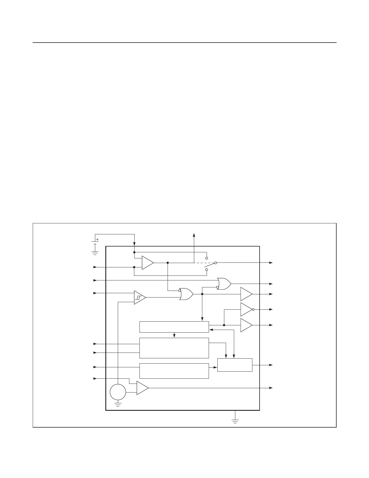
Figure 2. MAX696/MAX697 Block Diagram
4 GROUND
www.maximintegrated.com
Maxim Integrated │ 7
Share Link: 