MAX690 Просмотр технического описания (PDF) - Maxim Integrated
Номер в каталоге
Компоненты Описание
производитель
MAX690 Datasheet PDF : 18 Pages
| |||
MAX690–MAX695
Microprocessor Supervisory Circuits
General Description
The MAX690 family of supervisory circuits reduces the
complexity and number of components required for
power supply monitoring and battery control functions in
microprocessor systems. These include µP reset and
backup-battery switchover, watchdog timer, CMOS RAM
write protection, and power-failure warning. The MAX690
family significantly improves system reliability and accu-
racy compared to that obtainable with separate ICs or
discrete components.
The MAX690, MAX692, and MAX694 are supplied in
8-pin packages and provide four functions:
●● A reset output during power-up, power-down, and
brownout conditions.
●● Battery backup switching for CMOS RAM, CMOS
microprocessor or other low power logic.
●● A Reset pulse if the optional watchdog timer has not
been toggled within a specified time.
●● A 1.3V threshold detector for power fail warning, low
battery detection, or to monitor a power supply other
than +5V.
The MAX691, MAX693, and MAX695 are supplied in 16-pin
packages and perform all MAX690, MAX692, MAX694
functions, plus:
●● Write protection of CMOS RAM or EEPROM.
●● Adjustable reset and watchdog timeout periods.
●● Separate outputs for indicating a watchdog timeout,
backup-battery switchover, and low VCC.
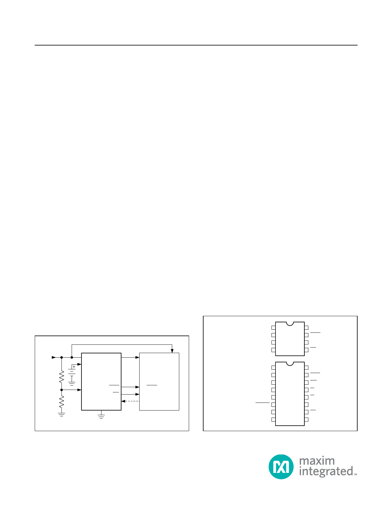
Typical Operating Circuit
+5V
VCC
VOUT
POWER TO
µP
VBATT
CMOS RAM POWER
MAX690
µP
SYSTEM
PFI
RESET
PFO
WDI
GND
µP RESET
µP NMI
I/O
LINE
MAX690 TYPICAL APPLICATION
Benefits and Features
●● Supervisory Function Integration Saves Board Space
while Fully Protecting Microprocessor-Based Systems
• Precision Voltage Monitor
-- 4.65V (MAX690, MAX691, MAX694, MAX695)
-- 4.40V (MAX692, MAX693)
• Power OK/Reset Time Delay
-- 50ms, 200ms, or Adjustable
• Watchdog Timer
-- 100ms, 1.6s, or Adjustable
• Battery Backup Power Switching
• Voltage Monitor for Power Fail or Low Battery
Warning
• Minimum External Component Count
●● Low Power Consumption in Battery Backup Mode
Extends Battery Life
• 1µA Standby Current
●● Onboard Gating of Chip Enable Signals Protects
Against Erroneous Data Written to RAM During Low
VCC Events
Applications
●● Computers
●● Controllers
●● Intelligent Instruments
●● Automotive Systems
●● Critical µP Power Monitoring
Ordering information appears at end of data sheet.
Pin Configurations
TOP VIEW
VOUT 1
VCC 2
GND 3
PFI 4
MAX690
MAX692
MAX694
8 VBATT
7 RESET
6 WDI
5 PFO
VBATT 1
VOUT 2
VCC 3
GND 4
BATT ON 5
LOW LINE 6
OSC IN 7
OSC SEL 8
MAX691
MAX693
MAX695
16 RESET
15 RESET
14 WDO
13 CE IN
12 CE OUT
11 WDI
10 PFO
9 PFI
19-0218; Rev 5; 4/15
Share Link: 