S-24C512C Просмотр технического описания (PDF) - Seiko Instruments Inc
Номер в каталоге
Компоненты Описание
производитель
S-24C512C Datasheet PDF : 35 Pages
| |||
2-WIRE SERIAL E2PROM
S-24C512C
Rev.2.0_02_S
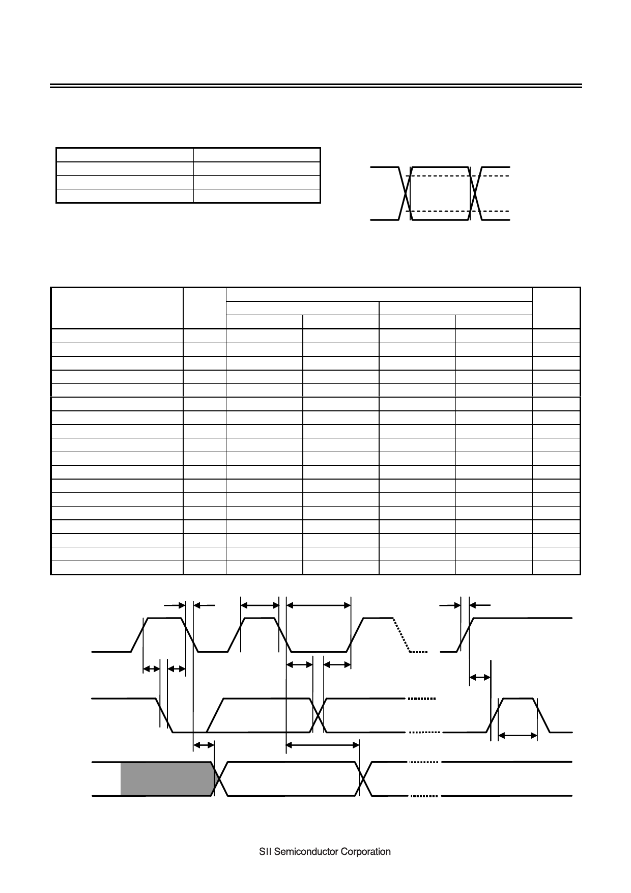
AC Electrical Characteristics
Table 11 Measurement Conditions
Input pulse voltage
Input pulse rising / falling time
Output reference voltage
Output load
0.2 × VCC to 0.8 × VCC
20 ns or less
0.3 × VCC to 0.7 × VCC
100 pF
Input pulse voltage
0.8 × VCC
Output reference voltage
0.7 × VCC
0.2 × VCC
0.3 × VCC
Figure 4 I/O Waveform during AC Measurement
Table 12
Ta = −40°C to +85°C
Item
Symbol
VCC = 2.5 V to 5.5 V
VCC = 1.6 V to 2.5 V
Unit
Min.
Max.
Min.
Max.
SCL clock frequency
fSCL
0
1000
0
400
kHz
SCL clock time “L”
tLOW
0.4
−
1.3
−
μs
SCL clock time “H”
tHIGH
0.3
−
0.6
−
μs
SDA output delay time
tAA
0.1
0.5
0.1
0.9
μs
SDA output hold time
tDH
50
−
50
−
ns
Start condition setup time
tSU.STA
0.25
−
0.6
−
μs
Start condition hold time
tHD.STA
0.25
−
0.6
−
μs
Data input setup time
tSU.DAT
80
−
100
−
ns
Data input hold time
tHD.DAT
0
−
0
−
ns
Stop condition setup time
tSU.STO
0.25
−
0.6
−
μs
SCL, SDA rising time
tR
−
0.3
−
0.3
μs
SCL, SDA falling time
tF
−
0.3
−
0.3
μs
WP setup time
tWS1
0
−
0
−
μs
WP hold time
tWH1
0
−
0
−
μs
WP release setup time
tWS2
0
−
0
−
μs
WP release hold time
tWH2
0
−
0
−
μs
Bus release time
tBUF
0.5
−
1.3
−
μs
Noise suppression time
tI
−
50
−
50
ns
tF
tHIGH
tLOW
tR
SCL
tSU.STA
tHD.STA
tHD.DAT
tSU.DAT
tSU.STO
SDA
(input)
tAA
tDH
tBUF
SDA
(output)
Figure 5 Bus Timing
6
Share Link: 