IRF720LPBF Просмотр технического описания (PDF) - Vishay Semiconductors
Номер в каталоге
Компоненты Описание
производитель
IRF720LPBF Datasheet PDF : 10 Pages
| |||
www.vishay.com
IRF720S, SiHF720S, IRF720L, SiHF720L
Vishay Siliconix
101
150 °C
100
25 °C
10-1
0.4
91044_07
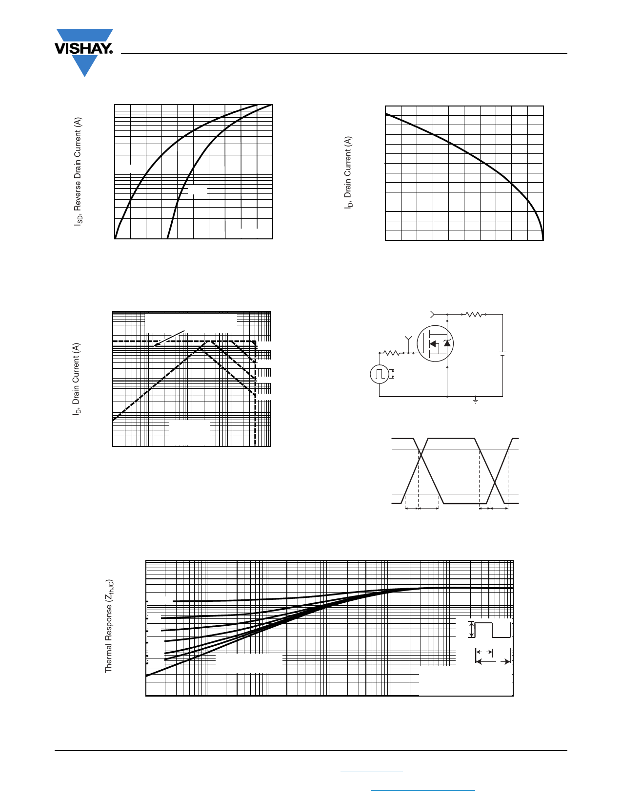
VGS = 0 V
0.6
0.8
1.0
1.2
1.4
VSD, Source-to-Drain Voltage (V)
Fig. 7 - Typical Source-Drain Diode Forward Voltage
102
5
2
10
5
2
1
5
2
0.1
5
2
10-2
0.1 2
Operation in this area limited
by RDS(on)
TC = 25 °C
TJ = 150 °C
Single Pulse
5 1 2 5 10 2 5 102 2
10 µs
100 µs
1 ms
10 ms
5 103
91044_08
VDS, Drain-to-Source Voltage (V)
Fig. 8 - Maximum Safe Operating Area
10
3.5
3.0
2.5
2.0
1.5
1.0
0.5
0.0
25
50
75
100
125
150
91044_09
TC, Case Temperature (°C)
Fig. 9 - Maximum Drain Current vs. Case Temperature
VDS
VGS
Rg
RD
D.U.T.
10 V
Pulse width ≤ 1 µs
Duty factor ≤ 0.1 %
+- VDD
Fig. 10a - Switching Time Test Circuit
VDS
90 %
10 %
VGS
td(on) tr
td(off) tf
Fig. 10b - Switching Time Waveforms
0 − 0.5
1
0.2
0.1
0.05
0.1 0.02
0.01
Single Pulse
(Thermal Response)
10-2
10-5
10-4
10-3
10-2
PDM
t1
t2
Notes:
1. Duty Factor, D = t1/t2
2. Peak Tj = PDM x ZthJC + TC
0.1
1
10
91044_11
t1, Rectangular Pulse Duration (s)
Fig. 11 - Maximum Effective Transient Thermal Impedance, Junction-to-Case
S20-0682-Rev. F, 07-Sep-2020
4
Document Number: 91044
For technical questions, contact: hvm@vishay.com
THIS DOCUMENT IS SUBJECT TO CHANGE WITHOUT NOTICE. THE PRODUCTS DESCRIBED HEREIN AND THIS DOCUMENT
ARE SUBJECT TO SPECIFIC DISCLAIMERS, SET FORTH AT www.vishay.com/doc?91000
Share Link: 