78P2241-IGT Просмотр технического описания (PDF) - TDK Corporation
Номер в каталоге
Компоненты Описание
производитель
78P2241-IGT Datasheet PDF : 23 Pages
| |||
FUNCTIONAL DESCRIPTION (continued)
LOSS OF SIGNAL
Should the input signal fall below a minimum value,
the loss of signal indication, LOS goes low.
B3ZS/HDB3 DECODER
The 78P2241 includes a selectable B3ZS/HDB3
Encoder/Decoder (ENDEC). When the ENDEC pin is
low, the ENDEC is selected and the receiver
generates a composite NRZ logic data following the
B3ZS (for DS3/STS-1) or HDB3 (for E3) substitution
codes via the RPOS/RNRZ pin as shown below.
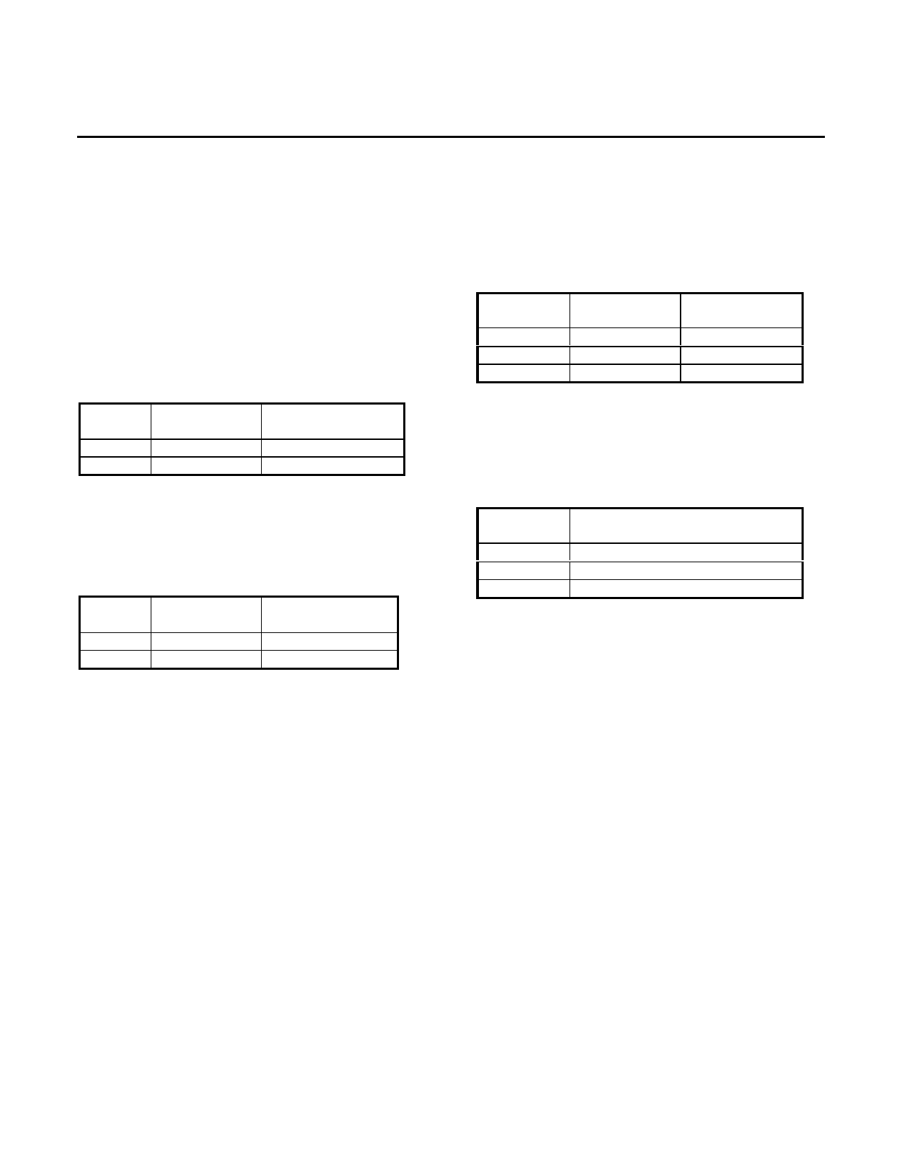
Pin 20
ENDEC
High
Low
RPOS/RNRZ
Positive AMI
NRZ data
RNEG
Negative AMI
No Connect
On the transmit side, NRZ input data is internally
converted to Positive and Negative logic data
following the B3ZS (for DS3/STS-1) or HDB3 (for E3)
substitution codes. The NRZ data is input to the
TPOS/TNRZ pin as shown below.
Pin 20
ENDEC
High
Low
TPOS/TNRZ
Positive AMI
NRZ data
TNEG
Negative AMI
No Connect
TRANSMITTER
The transmitter accepts logic level clock (TCLK),
positive data (TPOS) and negative data (TNEG)
signals and generates current pulses on the LOUT+
and LOUT- pins. When properly connected to a
center-tapped 1:2 transformer, an AMI pulse is
generated which can drive a 75Ω coaxial cable.
When the recommended transformer is used and the
E# pin is set high, the transmitted pulse shape at the
end of the 75Ω terminated cable of 0 to 450 feet will
fit the DS3 template in ANSI T1.102-1993 and
Telcordia GR-499-CORE standard documents.
For STS-1 applications, the transmitted pulse for a
short cable meets the requirements of Telcordia
GR-253-CORE. The E# pin should be allowed to
float.
78P2241
E3/DS3/STS-1
Transceiver
For E3 applications, the transmitted pulse for a short
cable meets the requirements of ITU-T G.703. The
E# pin is to be pulled low.
RCLK/TCLK polarity reversal:
To simplify the interface with framer circuitry, RCLK
and TCLK can be inverted with the ICKP pin.
Pin 10
ICKP
Low
Float
High
RCLK
Normal
Invert
Normal
TCLK
Normal
Invert
Invert
Loop-back modes:
The following loop-back modes allow for the
diagnostic test of the PC board. This function is
controlled by the LPBK pin.
Pin 28
LPBK
Low
Float
High
Loop-back
Local loop-back (LLB)
Remote loop-back (RLB)
Normal Operation
Local) loop-back:
When LPBK is low, the 78P2241 enters Local
loopback. In this mode, the LOUT+/- transmit signals
are internally routed to the receiver input circuit. The
incoming line receiver AMI signal on LIN+/- is
ignored. With the transmitter still tied to the cable,
this test mode can indicate a short circuit on the
transmitter external components or other problem in
the transmit path.
Remote loop-back:
When LPBK pin is allowed to float, the 78P2241
enters remote loopback mode. The RPOS/RNEG
and RCLK pins are internally tied to the
TPOS/TNEG and TCLK so the same AMI signal that
is received by the framer is transmitted back to the
far end where a bit continuity test can be performed.
Line Build-Out:
The Line Build-Out function controls the amplitude in
DS3 and STS-1 mode. The selection of LBO
depends on the amount of cable the transmitter is
connected to. When used with less than 225 ft of
cable the LBO pin should be pulled high. With 225ft
or more cable the LBO pin should be low.
3
Share Link: 