LT1374HVIR(RevA) Просмотр технического описания (PDF) - Linear Technology
Номер в каталоге
Компоненты Описание
производитель
LT1374HVIR Datasheet PDF : 28 Pages
| |||
LT1374
APPLICATIONS INFORMATION
(5)(15 − 5)
( ) 4.5 −
2
3.3
•
10−
6
500
•
103
15
= 4.5 − 1= 3.5A
Note that there is less load current available at the higher
input voltage because inductor ripple current increases.
This is not always the case. Certain combinations of
inductor value and input voltage range may yield lower
available load current at the lowest input voltage due to
reduced peak switch current at high duty cycles. If load
current is close to the maximum available, please check
maximum available current at both input voltage
extremes. To calculate actual peak switch current with a
given set of conditions, use:
(( )( )( ) ) ( ) ISW PEAK
=
IOUT
+
VOUT VIN
2L f
− VOUT
VIN
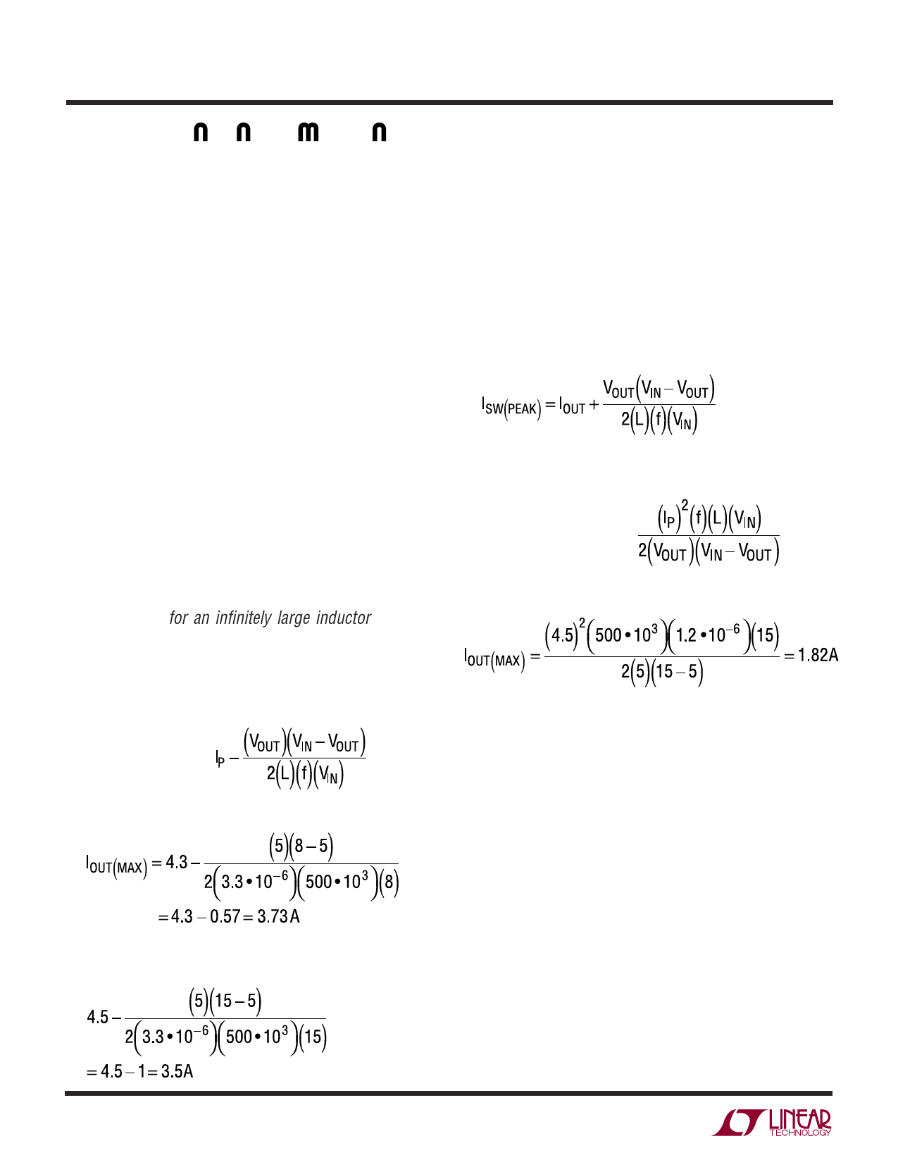
For lighter loads where discontinuous operation can be
used, maximum load current is equal to:
IOUT(MAX) =
(IP)2(f)(L)(VIN)
( )( ) Discontinuous mode 2 VOUT VIN − VOUT
Example: with L = 1.2µH, VOUT = 5V, and VIN(MAX) = 15V,
( ) ( )( ) ( ) ( ) IOUT MAX =
4.5
2
500
•
103
1.2
•
10−6
15
2 5 15 − 5
= 1.82A
The main reason for using such a tiny inductor is that it is
physically very small, but keep in mind that peak-to-peak
inductor current will be very high. This will increase output
ripple voltage. If the output capacitor has to be made larger
to reduce ripple voltage, the overall circuit could actually
wind up larger.
CHOOSING THE INDUCTOR AND OUTPUT CAPACITOR
For most applications the output inductor will fall in the
range of 3µH to 20µH. Lower values are chosen to reduce
physical size of the inductor. Higher values allow more
output current because they reduce peak current seen by
the LT1374 switch, which has a 4.5A limit. Higher values
also reduce output ripple voltage, and reduce core loss.
Graphs in the Typical Performance Characteristics section
show maximum output load current versus inductor size
and input voltage. A second graph shows core loss versus
inductor size for various core materials.
When choosing an inductor you might have to consider
maximum load current, core and copper losses, allowable
component height, output voltage ripple, EMI, fault cur-
rent in the inductor, saturation, and of course, cost. The
following procedure is suggested as a way of handling
these somewhat complicated and conflicting requirements.
1. Choose a value in microhenries from the graphs of
maximum load current and core loss. Choosing a small
inductor may result in discontinuous mode operation
at lighter loads, but the LT1374 is designed to work
well in either mode. Keep in mind that lower core loss
means higher cost, at least for closed core geometries
like toroids. The core loss graphs show both absolute
loss and percent loss for a 5W output, so actual percent
losses must be calculated for each situation.
Assume that the average inductor current is equal to
load current and decide whether or not the inductor
must withstand continuous fault conditions. If maxi-
mum load current is 0.5A, for instance, a 0.5A inductor
may not survive a continuous 4.5A overload condition.
Dead shorts will actually be more gentle on the induc-
tor because the LT1374 has foldback current limiting.
2. Calculate peak inductor current at full load current to
ensure that the inductor will not saturate. Peak current
can be significantly higher than output current, espe-
cially with smaller inductors and lighter loads, so don’t
omit this step. Powdered iron cores are forgiving
because they saturate softly, whereas ferrite cores
10
Share Link: 