MH88510 Просмотр технического описания (PDF) - Mitel Networks
Номер в каталоге
Компоненты Описание
производитель
MH88510 Datasheet PDF : 10 Pages
| |||
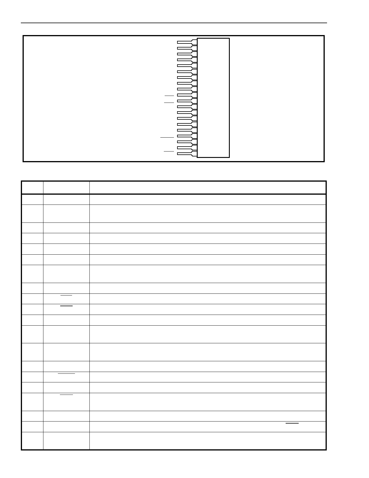
MH88510/11
Preliminary Information
Pin Description
Pin #
Name
1
TIP
2
VDD
3
RING
4
RF
5
TF
6
VBAT
7
AGND
8
VEE
9
LED
10
SHK
11
IC
12
VDD
13
AGND
14
VBAT
15
MUTE
16
JUNC
17
RRD
18
RGND
19
RRC
20
VRLY
TIP
1
VDD
2
RING
3
4
RF
5
TF
6
VBAT
7
AGND
8
VEE
9
10
LED
11
SHK
12
IC
13
VDD
14
AGND
15
VBAT
16
17
MUTE
18
JUNCTOR
19
RRD
20
Figure 2 - Pin Connections
Description
Tip Lead. Connects to the “Tip” lead (A-wire) of the telephone line.
Positive Power Supply Voltage. Normally +5V. This provides current for both internal
circuitry as well as the loop. Not internally connected to pin 12.
Ring Lead. Connects to the “Ring” lead (B-wire) of the telephone line.
Ring Feed. Connect to the Ring Relay contact. See Figure 5.
Leave open circuit
Battery Voltage Supply. Normally -24V or -48V. Not internally connected to pin 14.
Analog Ground. Supply and battery ground. Internally connected to pin 13. For
optimum performance connect pin 7 to pin 13.
Negative Power Supply Voltage. Normally -5V.
LED Drive (Output). Drives an LED directly. A logic low indicates an off-hook condition.
Switch Hook Detect (Output). A logic low indicates an off-hook condition.
Internal Connection. This pin is connected internally
Positive Power Supply Voltage. Normally +5V. This provides current for both internal
circuitry as well as the loop.
Analog Ground. Supply and battery ground. Internally connected to pin 13. For
optimum performance connect pin 13 to pin 7.
Battery Voltage Supply. Normally -24V or -48V. Not internally connected to pin 6.
MUTE (Input). A logic low will mute signals coming from Tip-Ring to the JUNC.
Receive/transmit audio speech path. (Referenced to 0V GND).
Ring Relay Drive (Output). Connects to the ring relay coil. A logic low activates the
relay.
Relay Ground. Return path for relay supply votlage. Normally connected to AGND.
Ring Relay Control (Input). A logic high activates the Ring Relay Drive (RRD) outputs.
Relay Positive Supply Voltage. Normally +5V. Connects to the relay coil and the relay
supply voltage. An internal clamp diode from VRLY to RGND is provided.
2-54
Share Link: 