EVAL-418-A Просмотр технического описания (PDF) - Radiometrix Ltd
Номер в каталоге
Компоненты Описание
производитель
EVAL-418-A Datasheet PDF : 11 Pages
| |||
Pin Description
pin 1 RF IN
The receiver antenna connects to this input. It has nominal RF
impedance of 50Ω and is capacitively isolated from the internal circuit
pin 2 RF GROUND This pin should be connected to any ground plane against which the
antenna works. It is internally connected to pin 4.
pin 3 DETECT
This pin may be used to derive a carrier detect to enable external circuits
when a signal is being received. If the detect function is not being used a
10 kΩ pull-up to pin 5 (Vcc) should be connected. Refer to applications
note for further details on the use of this pin.
pin 4 0 volt
Ground for supply.
pin 5 Vcc
Positive supply of 4V to 9V 13 mA. The supply must be clean (<2mV pp)
stable and free of high frequency digital noise. A supply filter is
recommended unless the module is driven from it’s own regulated supply.
pin 6 AF
This is the FM demodulator output. It has an standing DC bias of
approximately 1.4V and may be used to drive analogue data detectors
such as modem chips or DTMF decoders. Load impedances as low as 2 kΩ
and up to 100 pF can be driven
pin 7 DATA
.
This digital output from the internal data slicer is a squared version of
the signal on pin 6 (AF) This signal is used to drive external digital
decoders, it is true data (i.e. as fed to the transmitters data input). Load
impedances as low as 1 kΩ and up to 1 nF can be driven
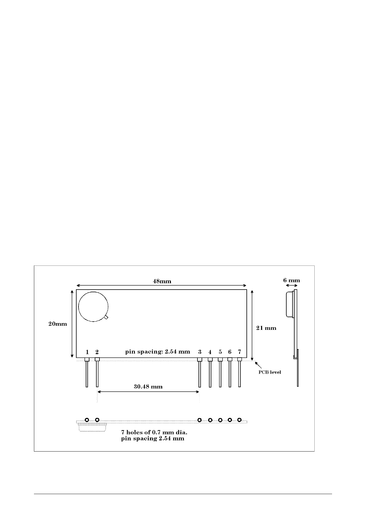
figure 3: Mechanical Dimensions:
Radiometrix Ltd, SILRX-UHF Data Sheet
page 3
Share Link: 