RMWD38001 Просмотр технического описания (PDF) - Fairchild Semiconductor
Номер в каталоге
Компоненты Описание
производитель
RMWD38001 Datasheet PDF : 8 Pages
| |||
RMWD38001
37-40 GHz Driver Amplifier MMIC
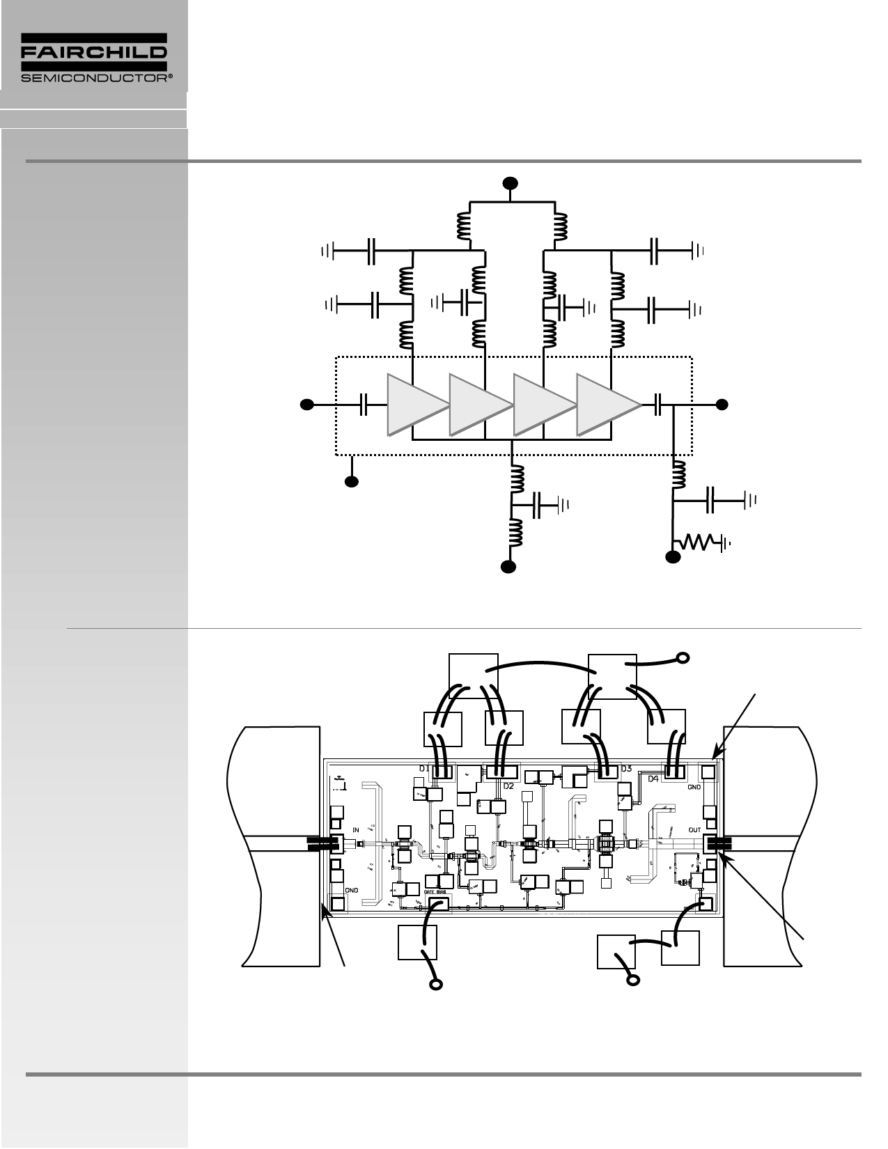
Figure 3
Recommended
Application Schematic
Circuit Diagram
10,000pF
Drain Supply
Vd = +4 V
L
PRODUCT INFORMATION
L = Bond Wire Inductance
L
10,000pF
RF IN
L
100pF
L
MMIC Chip
L
100pF
L
L
100pF
L
L
100pF
L
RF OUT
Figure 4
Recommended
Assembly Diagram
Ground
(Back of Chip)
L
100pF
L
100pF
L
L
3 kΩ
Gate Supply
Vg
Output Power
Detector Voltage
Vdet
Note:
Detector delivers 0.1 V DC into 3k Ω load resistor for >+17 dBm output power. If output power level detection is not desired, do not make
connection to detector bond pad.
10,000pF
10,000pF
Vd
(Positive)
100pF
100pF
Die-Attach
80Au/20Sn
5mil Thick
Alumina
50-Ohm
100pF
100pF
5 mil Thick
Alumina
50-Ohm
RF
Input
RF
Output
100pF
100pF
3kΩ
L< 0.015”
(4 Places)
2 mil
Gap
Vg
(Negative)
Detector Voltage
Notes:
Use 0.003” by 0.0005” Gold Ribbon for bonding. RF input and output bonds should be less than 0.015” long with stress relief.
Detector delivers 0.1V DC into 3k Ω load resistor for >+17 dBm output power. If output power level detection is not desired, do not make
connection to detector bond pad
Characteristic performance data and specifications are subject to change without notice.
Revised March 14, 2001
Page 3
Share Link: 