MH88520-1 Просмотр технического описания (PDF) - Mitel Networks
Номер в каталоге
Компоненты Описание
производитель
MH88520-1 Datasheet PDF : 10 Pages
| |||
Preliminary Information
MH88520-1
Functional Description
The BORSH Functions
The MH88520-1 performs all of the Borsh functions
of Battery Feed Overvoltage Protection, Ringing,
Supervision and Hybrid (2-2 Wire).
Return Loss at Tip-Ring
the SLIC, and converts the ground referenced input
signal at JUNC of the SLIC into the non-balanced
output signal at Tip-Ring of the telephone line.
Mute
A logic low at the MUTE input results in muted
signals coming from Tip and Ring to the JUNC
terminal while allowing signals from the JUNC
terminal to Tip and Ring to be transmitted.
To maximise return loss, the impedance at Tip-Ring
should match the SLIC’s impedance (220R + 820R //
115nF). However, the SLIC’s input impedance is
dependent on the JUNCTOR termination resistance.
Therefore the JUNCTOR must be terminated with
754Ω.
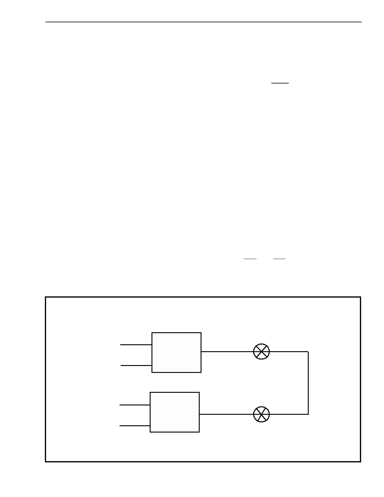
Figure 3 illustrates a typical connection between two
SLICs through two crosspoint switches. Optimum
return loss occurs when the JUNCTOR is terminated
with 754Ω. Since the JUNCTOR input/output
impedances is 604Ω and the crosspoint switch
resistances are 75Ω + 75Ω, this configuration gives
optimum return loss as shown in Figure 4.
Hybrid
The 2-2 wire hybrid circuit converts the incoming
balanced signal at Tip and Ring of the telephone line
into a ground referenced output signal at JUNC of
Overvoltage Protection
The MH88520-1 is protected from short term (1ms)
(+250V) between Tip and Ring, Tip and Ground, and
Ring and Ground. However, additional protection
circuitry may be needed depending upon the
requirements which must be met for the final
equipment.
Loop Detection
The loop detection circuit determines whether a low
enough path is across Tip and Ring to be recognised
as an off-hook condition. (Threshold impedance =
5.4kΩ with no adjustment). This threshold level can
be adjusted by the use of external resistors as
shown in Figure 6. When an off-hook condition
occurs the SHK and LED outputs toggle to a logic
low level. These outputs also toggle during incoming
dial pulses.
TIP
RING
TIP
RING
1 MH88520-1
TIP
16
JUNC
3
RING
SLIC 1
1 MH88520-1
TIP
16
JUNC
8
RING
SLIC 2
75Ω
CROSSPOINT
SWITCH
75Ω
CROSSPOINT
SWITCH
Figure 3 - SLIC Crosspoint Switch Connection
2-65
Share Link: 