MH88622-2 Просмотр технического описания (PDF) - Mitel Networks
Номер в каталоге
Компоненты Описание
производитель
MH88622-2 Datasheet PDF : 10 Pages
| |||
Preliminary Information
MH88622
Functional Description
The SLIC uses a Transformerless 2-4 Wire converter
for each subscriber which can be connected to a
CODEC to interface the 2-Wire subscriber loop to a
time division multiplexed (TDM), pulse code
modulated (PCM), digital link.
Powering of the subscriber line is provided through
precision battery feed resistors on the hybrid. The
thick film hybrid circuit contains control, signalling
and status circuits which combine to provide a
complete solution simplifying the manufacture of line
cards.
Approvals
FCC part 68, CCITT, DOS CS-03, UL 1459, CAN/
CSA-22.2 N0. 225-M90 and ANSI/EIA/TIA-464-A are
system level safety standards and performance
requirements. As a component of a system, the
MH88622 is designed to comply with the applicable
requirements of these specifications.
Battery Feed
The SLIC is designed for a nominal battery voltage
of -48 Vdc and can provide the constant feed current
for 1500Ω loop under this condition.
The interface circuit is designed to be operated up to
a maximum of -60V dc battery feed voltage without
damage, providing a minimum loop length capability
of 2000Ω.
There is also a function on the SLIC that provides for
Tip-Ring reversal.
Current Limit
Primary over current protection is inherent in the
current limiting feature of the battery feed circuit.
Current limiting is provided for both Tip and Ring
unbalanced conditions.
The maximum loop current limit is set internally on
the interface and current limiting does not affect the
longitudinal or the signal balance of the device. To
set ILoop to 40mA tie the LCS pin high (Logic 1), to
set ILoop to 25mA the LCS pin may be left open circuit
or tied low (Logic 0).
Two Wire Port Termination Impedance
The Tip/Ring impedance (Zin) is fixed for each
variant.
Transmit and Receive Gain
The transmit and receive gain of the MH88622 is
internally set.
Internal Ringing Generator
The MH88622 offers an on board ringing generator
requiring only two external passive components and
a DC voltage source to produce a sine wave of
between 17Hz to 68Hz.
An internal signal is amplified by a user programmed
amount and is applied to Tip and Ring. The
programmable gain must be set using RGV and RG1
to ensure that distortion of the ringing signal is
minimised.
With VBAT = -48Vdc and VDCRI = +120Vdc and the
ringing voltage = 90Vrms RGV and RG1 should be left
open circuit. By adding an external resistor between
RGV and RG1 it is possible to reduce the ringing
voltage applied by the driver section to Tip and Ring.
The DC voltage source should be continuously applied
to the MH88622. The ringing voltage will only be
applied when the RC pin of the relevant subscriber is
activated.
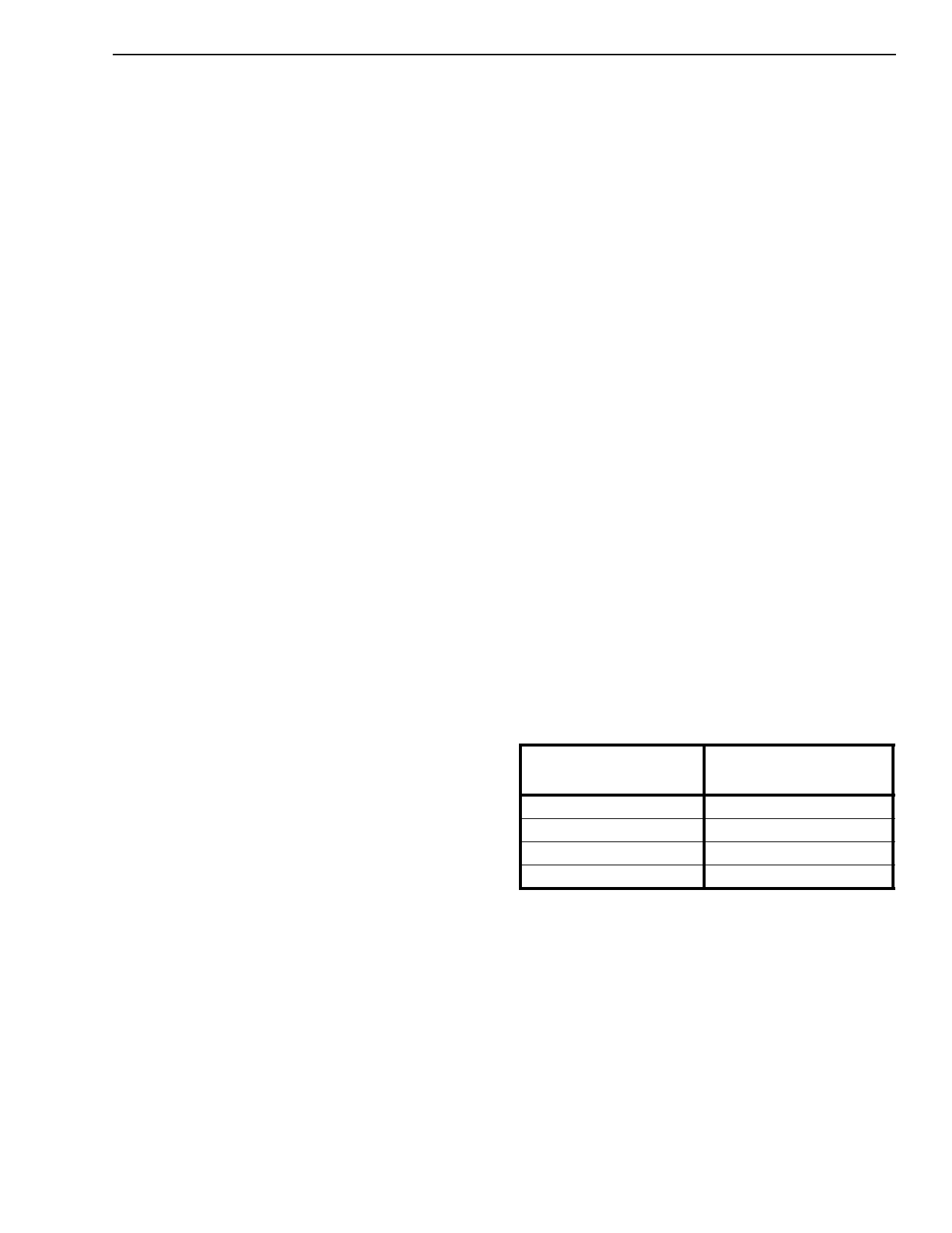
Typ. Frequency
(Hz)
CF1, CF2
(nF)
17
100
25
68
35
47
50
33
Table 1 - Ring Generator Capacitor Selection
12-16kHz Meter Pulse
The MH88622 provides control of an external signal
path to the driver. A 12/16 KHz continuous signal
should be applied to the ESI pin. Control of the ESE
input allows the metering signal to be transmitted to
the line with a ramped up and down amplitude to
reduce noise on the line. Typical ramp time is 10mS.
2-179
Share Link: 