MH88622-5 Просмотр технического описания (PDF) - Mitel Networks
Номер в каталоге
Компоненты Описание
производитель
MH88622-5 Datasheet PDF : 10 Pages
| |||
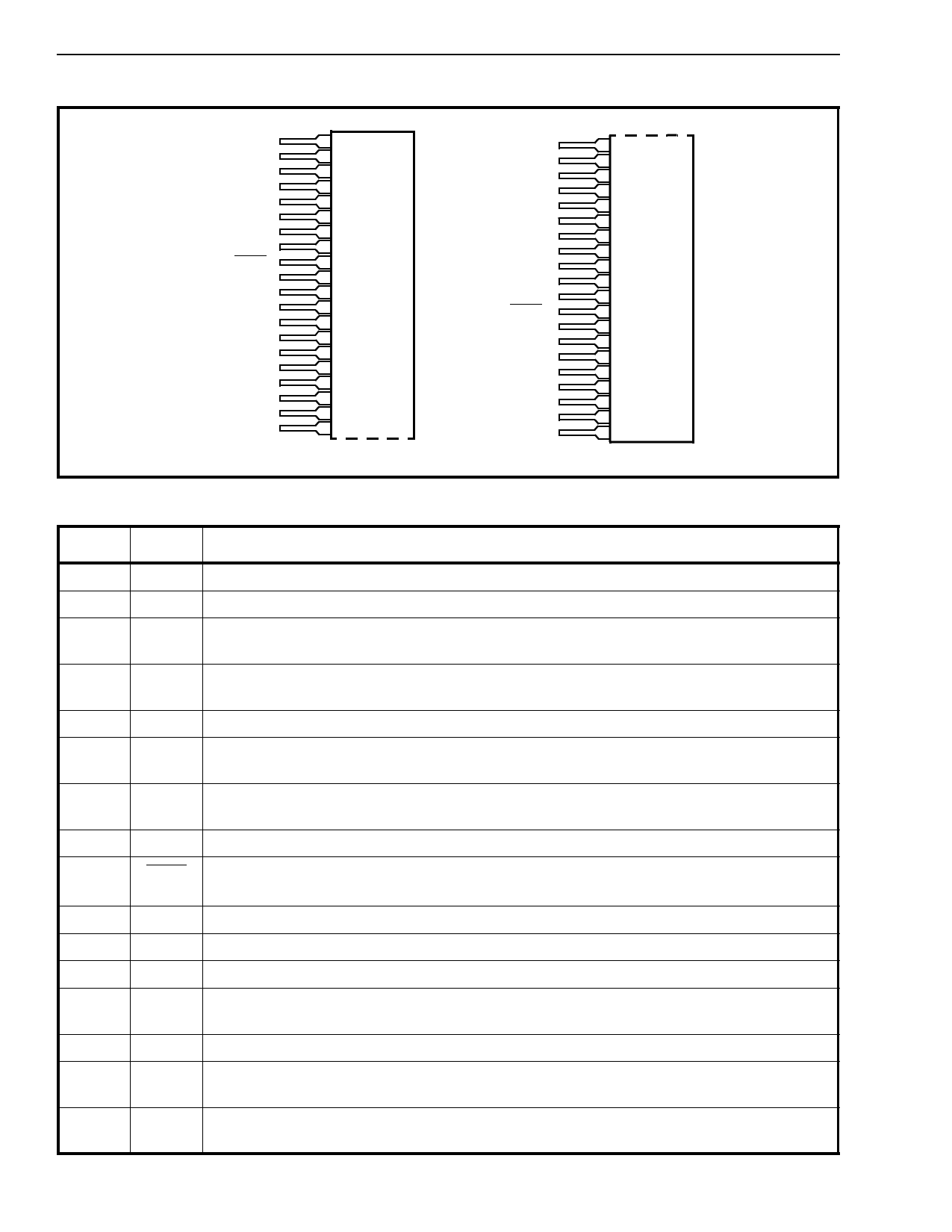
MH88622
Preliminary Information
TIP1
1
RING1
2
VBAT
3
DCRI
4
GND
5
ESI1
6
ESE1
7
VR1
8
SHK1
9
LCS1
10
VX1
11
VEE
12
GND
13
VDD
14
LR1
15
RC1
16
NC
17
NC
18
RF1
19
RF2
20
RGV
21
RG1
22
NC
23
NC
24
RC2
25
LR2
26
VDD
27
GND
28
VEE
29
VX2
30
LCS2
31
SHK2
32
VR2
33
ESE2
34
ESI2
35
GND
36
DCRI
37
VBat
38
RING2
39
TIP2
40
Pin Description
Figure 2 - Pin Connections
Pin # Name
Description
1
TIP1 Tip Lead. Connects to the “TIP” lead of subscriber line 1.
2
RING1 Ring Lead. Connects to the “RING” lead of subscriber line 1.
3
VBAT Battery Voltage. Typically -48V dc is applied to this pin. This should be connected to pin 38
of the hybrid on the PCB.
4
DCRI DC Ringing Voltage Input. A continuous 120V dc is applied to this input to achieve
90Vrms ringing. This should be connected to pin 37 of the hybrid.
5
GND Ground. This pin should be tied to pins 13, 28 & 36 on the PCB.
6
ESI1 External Signal Input (Input). A continuous signal should be applied to this pin which will
be switched to “Tip” and “Ring” of subscriber 1.
7
ESE1 External Signal Enable (Input). The external signal to the subscriber 1 is controlled by a
logic level applied to this pin.
8
VR1 Receive (Input). 4-Wire GND referenced audio input for subscriber 1.
9
SHK1 Off Hook Indication (Output). A logic low output indicates when subscriber 1 equipment
has gone off hook.
10
LCS1 Loop Current Set 1. Logic 1 gives ILoop = 40mA, Logic 0 gives ILoop = 25mA
11
VX1 Transmit (Output). 4-Wire, GND referenced audio output for subscriber 1.
12
VEE Negative Supply Voltage. -5Vdc. Connects to pin 29 of the hybrid on the PCB.
13
GND Ground. Return path for VDD, VEE, VBat & DCRI. This pin should be connected to pins 5,
28 & 36 of the hybrid on the PCB.
14
VDD Positive Supply Voltage. +5Vdc. Connect to pin 27 of the hybrid on the PCB.
15
LR1 Line Reversal. A logic 1 applied to LR1 will reverse the “Tip” and “Ring” to subscriber 1.
This pin has an internal pull down.
16
RC1 Ringing Control (Input). A logic level applied to this pin enables ringing to be applied
across Tip and Ring of subscriber 1.
2-174
Share Link: 