M65677FP Просмотр технического описания (PDF) - MITSUBISHI ELECTRIC
Номер в каталоге
Компоненты Описание
производитель
M65677FP Datasheet PDF : 6 Pages
| |||
MITSUBISHI ICs (TV)
M65677FP
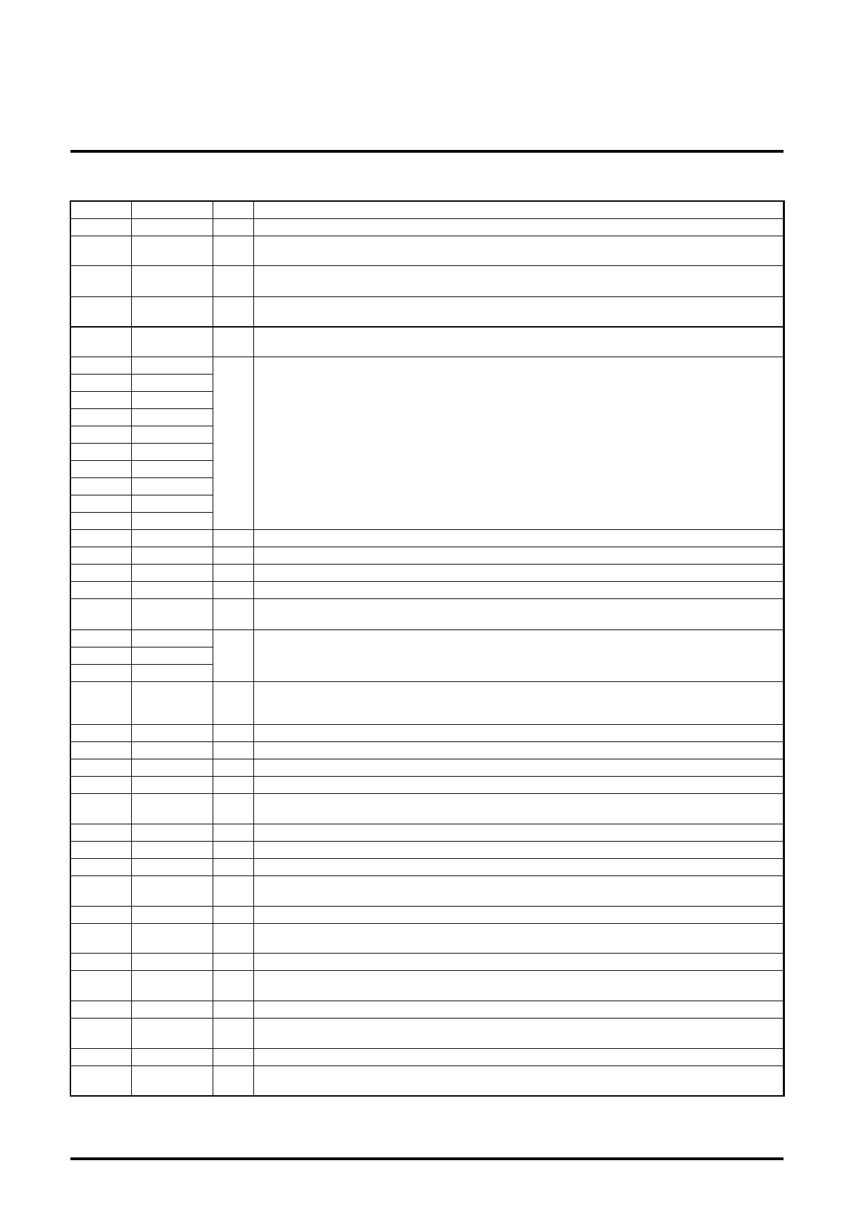
DIGITAL NTSC/PAL ENCODER
DESCRIPTION OF PIN
Pin No.
1
2
3
4
5
6
7
8
9
10
11
12
13
14
15
16
17
18
19
20
21
22
23
24
25
26
27
28
29
30
31
32
33
34
35
36
37
38
39
40
41
Pin name
DV SS2
PXCLK
DVA SEL
HD
VD
VD9
VD8
VD7
VD6
VD5
VD4
VD3
VD2
VD1
VD0
DV SS2
DV DD2
DV DD1
DV SS1
OSDCK
OSD0
OSD1
OSD2
Master/Slave
RESET
ACK
SDA
SCL
TEST
DV DD1
N.C.
N.C.
C
N.C.
CVBS
AV SS2
Y
AV DD2
Yin
N.C.
Cin
Type
Supply
O
I
I/O
I/O
I/O
Supply
Supply
Supply
Supply
O
I
I
I
O
I/O
I
I
Supply
O
O
Supply
O
Supply
I
I
Function
Digital ground for the I/O.
Reference clock for input pixel data.
The clock frequency is 27.0MHz.
I2C slave address setting.
"Low" is for the address of 40h, "High" is for the address of 42h.
Horizontal sync signal input or output.
It is an input and output in the slave and master mode, respectively.
Vertical sync input or output. Or OddEven signal output.
It is an input and output in the slave and master mode, respectively.
Video data outputs.
In the Y/U/V output mode, the output is the 10-bit digital luma signal with a composite sync.
VD9 is MSB and VD0 is LSB.
Digital ground for the I/O.
Digital supply for the I/O.
Digital supply for the internal logic.
Digital ground for the internal logic.
The reference clock for an external OSD microcontroller.
The frequency is 13.5MHz or 6.25MHz, alternated by the I2C bus control.
The color look-up table address input.
MSB and LSB is OSD2 and OSD0, respectively.
Synchronizing mode selection.
"Low" is for the slave mode.
"High" is for the master mode.
Initializing reset. "LOW" is active.
Acknowledge line (Open drain output).
Serial data line/Acknowledge line (Open drain output).
Serial clock line.
For testing.
It should be grounded during an actual use.
Digital supply for the internal logic.
No connection.
No connection.
The analog chroma output from a 6dB amplifier.
The output amplitude is 1.0VP-P (typ.), while the input is 0.5VP-P.
No connection.
The analog composite video signal from a 6dB amplifier.
The output amplitude is 1.24VP-P (typ.).
Analog ground for 6dB amplifiers.
The analog luma output from a 6dB amplifier.
The output amplitude is 1.2VP-P (typ.), while input is 0.6VP-P.
Analog supply for 6dB amplifiers.
The analog luma input from an external LPF.
This input has bias circuit. The signal must input via a capacitor.
No connection.
The analog chroma input from an external LPF.
This input has bias circuit. The signal must input via a capacitor.
4
Share Link: 