ADN4690E_ Просмотр технического описания (PDF) - Analog Devices
Номер в каталоге
Компоненты Описание
производитель
ADN4690E_ Datasheet PDF : 12 Pages
| |||
Application Note
AN-1177
BUS TYPES AND TOPOLOGIES
Standard TIA/EIA-644 LVDS devices allow low power, high
speed communication. The advantages of LVDS can also
be applied to multipoint applications by using TIA/EIA-899
devices. Bus topology is one of the main factors relating to
which LVDS or M-LVDS devices are used in an application.
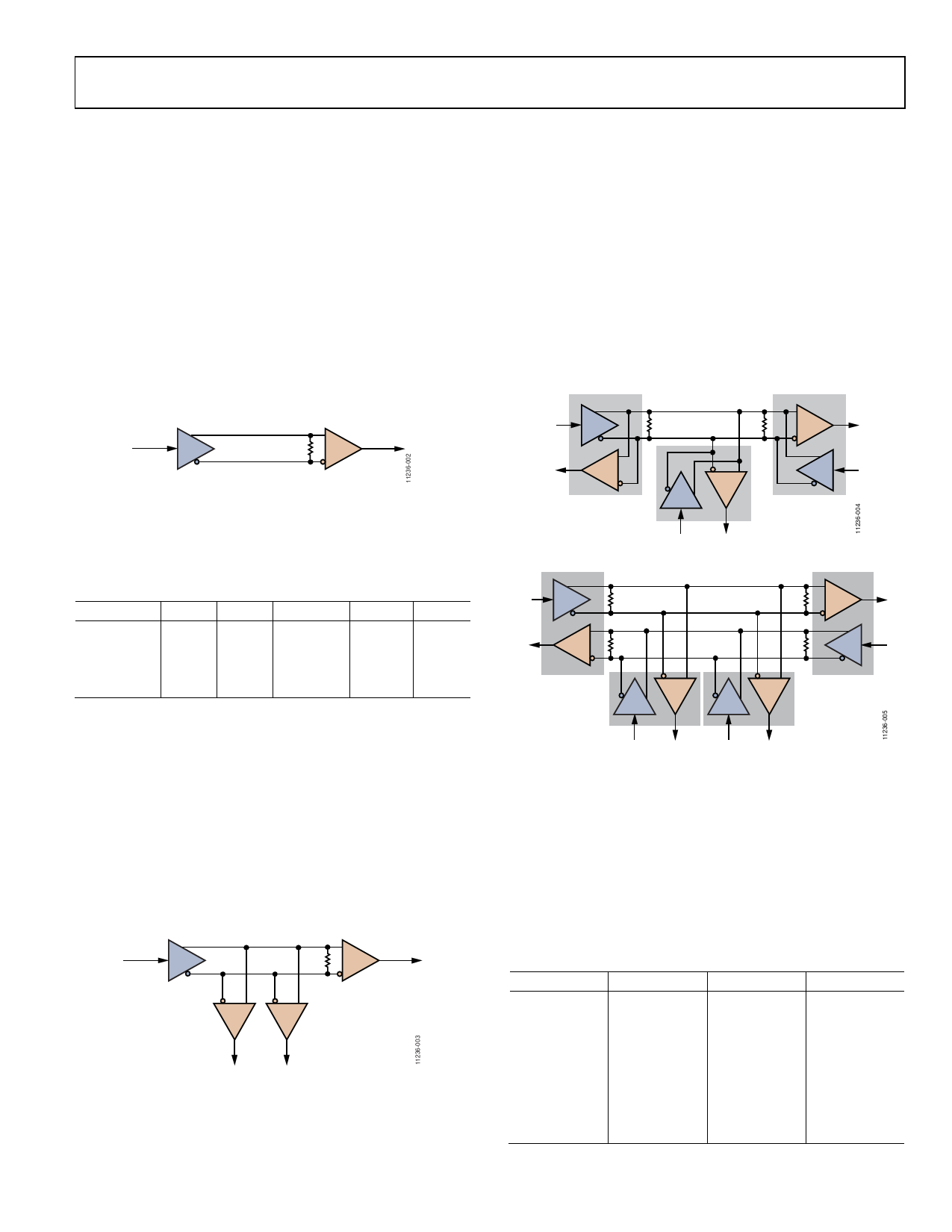
POINT-TO-POINT
Point-to-point bus topologies consist of a single driver and single
receiver connected together using one pair of wires or traces.
Figure 2 demonstrates a typical configuration, where the receiving
end of the link has a termination resistor. This is the most common
application for LVDS devices. Multiple pairs of wires or traces
can be used to create additional channels of communication and
increase total bandwidth between two points.
DOUT+
DIN
RIN+
RT
ROUT
LVDS
DRIVER
DOUT–
RIN–
LVDS
RECEIVER
Figure 2. LVDS Point-to-Point Link
Analog Devices, Inc., has a portfolio of LVDS drivers and receivers
for one, two or four LVDS channels as shown in Table 1. Unused
outputs should be left open circuit.
Table 1. LVDS Drivers and Receivers
Part No. Tx
Rx
Part No. Tx
Rx
ADN4661 1
0
ADN4665 4
0
ADN4662 0
1
ADN4666 0
4
ADN4663 2
0
ADN4667 4
0
ADN4664 0
2
ADN4668 0
4
M-LVDS can also be used in a point-to-point topology, where the
same transceiver device is used for the driver circuit (with receiver
disabled) and the receiving circuit (with driver disabled).
MULTI-DROP
A single driver can be connected to multiple receivers using
a multi-drop bus topology as shown in Figure 3. LVDS is
designed for point-to-point applications and so in a multi-drop
configuration, the number of receivers that can be connected
and the signaling distance can be limited. M-LVDS can be used
in a multi-drop topology to drive up to 32 nodes across longer
distances compared to LVDS.
DOUT+
DIN
RIN+
RT
LVDS
DRIVER
DOUT–
RIN–
LVDS
RECEIVERS
ROUT
ROUT
Figure 3. LVDS Multi-Drop Bus
MULTIPOINT
In networks where multiple devices can either send or receive,
a multipoint bus topology may be used. M-LVDS is designed
for such multi-point applications, allowing up to 32 nodes to
be connected to a single bus. There are two types of multipoint
buses, half-duplex and full duplex, shown in Figure 4 and
Figure 5, respectively. In a half-duplex bus, two wires are used
such that one device may transmit, and the other devices can
receive. In a full-duplex bus, four wires are used, allowing one
node to concurrently transmit back to another transmitting
node (that is, slave devices responding as broadcast commands
are sent by the master to all nodes).
A
A
DI
RO
RT
RT
B
RO
B
DI
MLVDS
TRANSCEIVERS
DI
RO
Figure 4. M-LVDS Half-Duplex Bus
Y
DI
RT
Z
RO
A RT
B
MLVDS
TRANSCEIVERS
A
RO
RT B
Y
DI
RT
Z
DI
RO
DI
RO
Figure 5. M-LVDS Full-Duplex Bus
Another factor to be considered in multipoint buses is the bus
idle condition. When no device is transmitting, the differential
voltage on a terminated bus will be close to 0 V. This means that
for a standard receiver with symmetrical input thresholds, the
receiver output will be undefined. This corresponds to the
Type 1 M-LVDS receivers with an input threshold of ±50 mV.
In order to provide a guaranteed receiver output state (output
low) in the bus idle condition, Type 2 M-LVDS receivers have
an offset receiver input threshold of +50 mV to +150 mV.
Table 2. M-LVDS Transceivers
Part No.
Rx Type
Duplex
ADN4690E
1
Half
ADN4691E
1
Half
ADN4692E
1
Full
ADN4693E
1
Full
ADN4694E
2
Half
ADN4695E
2
Full
ADN4696E
2
Half
ADN4697E
2
Full
Data Rate
100
200
100
200
100
100
200
200
Rev. 0 | Page 3 of 12
Share Link: 