SK106 Просмотр технического описания (PDF) - New Jersey Semiconductor
Номер в каталоге
Компоненты Описание
производитель
SK106 Datasheet PDF : 1 Pages
| |||
iodacti, Una..
20 STERN AVE.
TELEPHONE: (973) 376-2922
SPRINGFIELD, NEW JERSEY 07081
U.S.A.
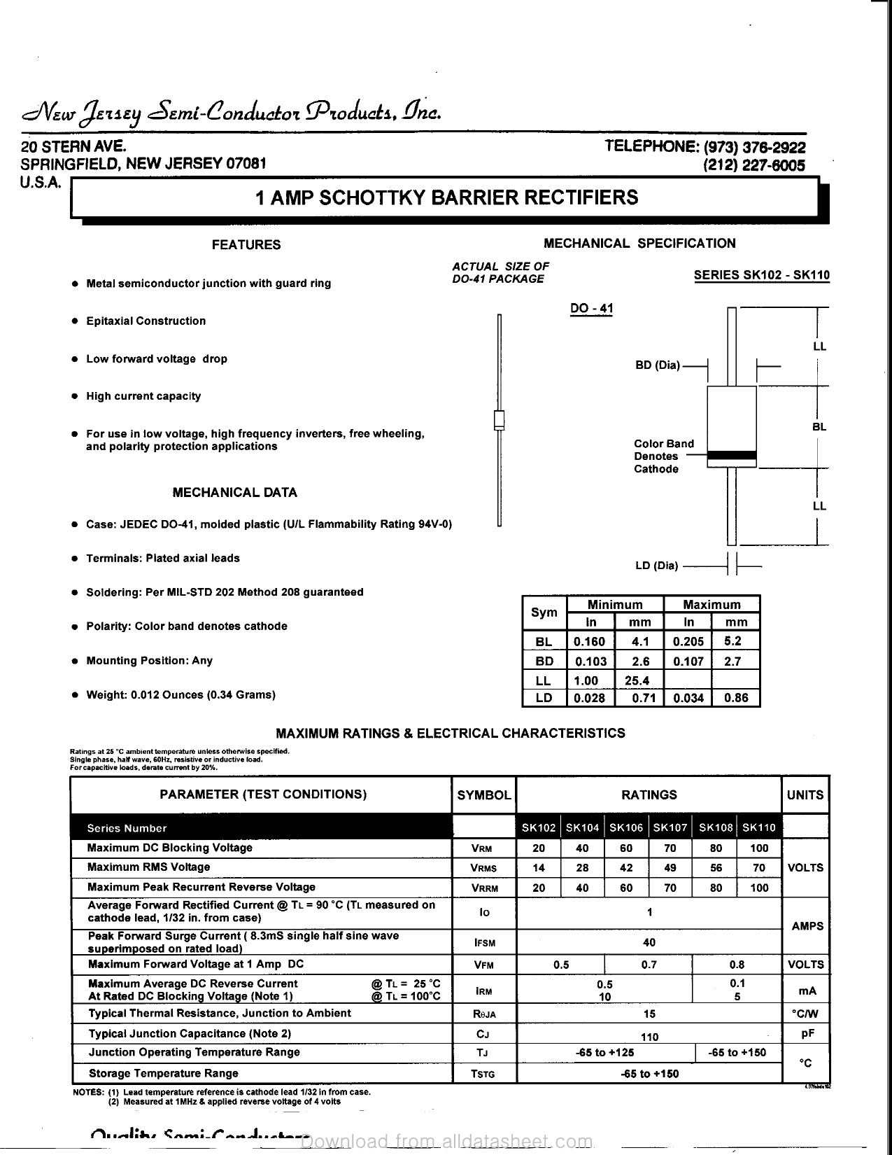
1 AMP SCHOTTKY BARRIER RECTIFIERS
j (212)227-6005
FEATURES
• Metal semiconductor junction with guard ring
• Epitaxial Construction
• Low forward voltage drop
MECHANICAL SPECIFICATION
ACTUAL SIZE OF
DO-41 PACKAGE
SERIES SKI 02.-SK110
DO-41
LL
BD(Dia)-
• High current capacity
Q
For use in low voltage, high frequency inverters,free wheeling,
and polarity protection applications
MECHANICAL DATA
• Case: JEDEC DO-41, molded plastic (U/L FlammabilityRating 94V-0)
BL
Color Band
Denotes
Cathode
LL
• Terminals: Plated axial leads
• Soldering: Per MIL-STD 202 Method 208 guaranteed
• Polarity: Color band denotes cathode
• Mounting Position: Any
• Weight: 0.012 Ounces (0.34 Grams)
LD (Dia)
Sym
BL
BD
LL
LD
Minimum
In mm
0.160 4.1
0.103 2.6
1.00 25.4
0.028 0.71
Maximum
In mm
0.205 5.2
0.107 2.7
0.034 0.86
MAXIMUM RATINGS & ELECTRICAL CHARACTERISTICS
Ratings at 25 °C ambient temperature unless otherwise specified.
Single phase, half wave, 60Hz, resistive or inductive load.
Forcapacttive loads, derate current by 20%.
PARAMETER (TEST CONDITIONS)
SYMBOL
RATINGS
UNITS
Series Number
^^^^^| SK102 SK104 SK106 SK107 SK108 SK110 HH
Maximum DC Blocking Voltage
VRM
20
40
60
70
80 100
Maximum RMS Voltage
VRMS
14
28
42
49
56
70 VOLTS
Maximum Peak Recurrent Reverse Voltage
Average Forward Rectified Current @ Ti_ = 90 °C (Ti_ measured on
cathode lead, 1/32 in. from case)
Peak Forward Surge Current ( 8.3mS single half sine wave
superimposed on rated load)
Maximum Forward Voltage at 1 Amp DC
VRRM
lo
IFSM
VFM
20
40
05
60
70
1
40
0.7
80 100
AMPS
0.8
VOLTS
Maximum Average DC Reverse Current
At Rated DC Blocking Voltage (Note 1)
@ Ti_ = 25 °C
@ TL = 100"C
IRM
Typical Thermal Resistance, Junction to Ambient
ROJA
0.5
10
15
0.1
5
mA
°C/W
Typical Junction Capacitance (Note 2)
Junction Operating Temperature Range
Storage Temperature Range
Cj
TJ
TSTG
110
PF
-65 to +125
-65 to +150
"C
-65 to +150
NOTES: (1) Lead temperature reference is cathode lead 1/32 In from case.
(2) Measured at 1MHz & applied reverse voltage of 4 volts
( 11 I*^I|4«* ^f*W*t — S A»* JB • .»&^»«
Share Link: 