ISL85410 Просмотр технического описания (PDF) - Renesas Electronics
Номер в каталоге
Компоненты Описание
производитель
ISL85410 Datasheet PDF : 21 Pages
| |||
ISL85410
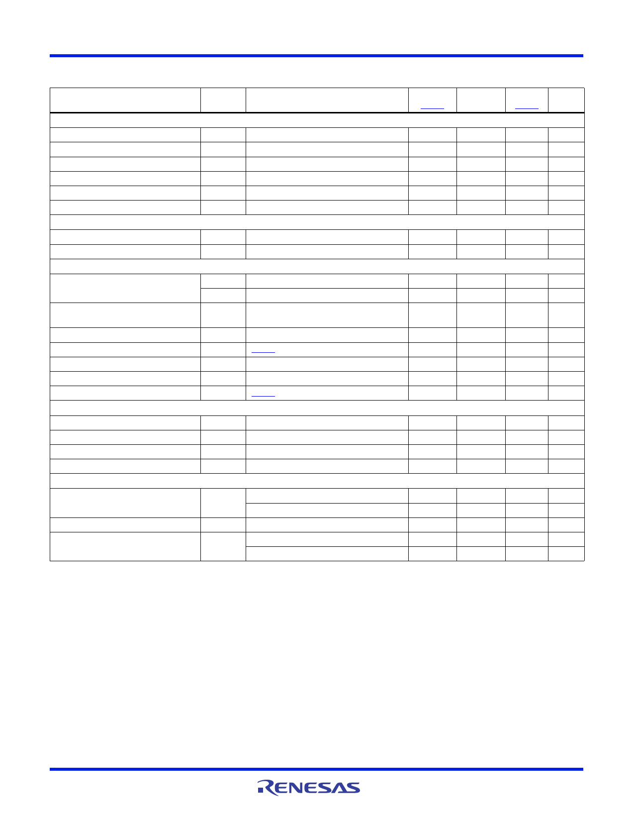
Electrical Specifications TA = -40°C to +125°C, VIN = 3V to 40V, unless otherwise noted. Typical values are at TA = +25°C. Boldface
limits apply across the junction temperature range, -40°C to +125°C (Continued)
PARAMETER
SYMBOL
TEST CONDITIONS
MIN
(Note 9)
MAX
TYP
(Note 9) UNITS
POWER-GOOD
Lower PG Threshold - VFB Rising
90
94
%
Lower PG Threshold - VFB Falling
82.5
86
%
Upper PG Threshold - VFB Rising
116.5
120
%
Upper PG Threshold - VFB Falling
107
112
%
PG Propagation Delay
Percentage of the soft-start time
10
%
PG Low Voltage
TRACKING AND SOFT-START
ISINK = 3mA, EN = VCC, VFB = 0V
0.05
0.3
V
Soft-Start Charging Current
Internal Soft-Start Ramp Time
FAULT PROTECTION
ISS
EN/SS = VCC
4.2
5.5
6.5
µA
1.5
2.4
3.4
ms
Thermal Shutdown Temperature
Current Limit Blanking Time
TSD
THYS
tOCON
Rising threshold
Hysteresis
150
°C
20
°C
17
Clock
pulses
Overcurrent and Auto Restart Period
Positive Peak Current Limit
tOCOFF
IPLIMIT (Note 8)
8
SS cycle
1.3
1.5
1.7
A
PFM Peak Current Limit
Zero Cross Threshold
IPK_PFM
0.34
0.4
0.5
A
15
mA
Negative Current Limit
INLIMIT (Note 8)
-0.67
-0.6
-0.53
A
POWER MOSFET
High-side
Low-side
PHASE Leakage Current
RHDS
RLDS
IPHASE = 100mA, VCC = 5V
IPHASE = 100mA, VCC = 5V
EN = PHASE = 0V
250
350
mΩ
90
130
mΩ
300
nA
PHASE Rise Time
EN/SYNC
tRISE VIN = 40V
10
ns
Input Threshold
Falling edge, logic low
0.4
1
V
Rising edge, logic high
1.2
1.4
V
EN Logic Input Leakage Current
EN = 0V/40V
-0.5
0.5
µA
SYNC Logic Input Leakage Current
SYNC = 0V
10
100
nA
SYNC = 5V
1.0
1.55
µA
NOTES:
7. Test Condition: VIN = 40V, FB forced above regulation point (0.6V), no switching and power MOSFET gate charging current not included.
8. Established by both current sense amplifier gain test and current sense amplifier output test at IL = 0A.
9. Parameters with MIN and/or MAX limits are 100% tested at +25°C, unless otherwise specified. Temperature limits established by characterization
and are not production tested.
10. Minimum On-Time required to maintain loop stability.
FN8375 Rev 7.00
March 13, 2015
Page 7 of 21
Share Link: 