MT16VDDF12864HG-40B Просмотр технического описания (PDF) - Micron Technology
Номер в каталоге
Компоненты Описание
производитель
MT16VDDF12864HG-40B Datasheet PDF : 15 Pages
| |||
512MB, 1GB (x64, DR) 200-Pin DDR SODIMM
Electrical Specifications
Electrical Specifications
Stresses greater than those listed in Table 7 may cause permanent damage to the
module. This is a stress rating only, and functional operation of the module at these or
any other conditions outside those indicated on the device data sheet is not implied.
Exposure to absolute maximum rating conditions for extended periods may adversely
affect reliability.
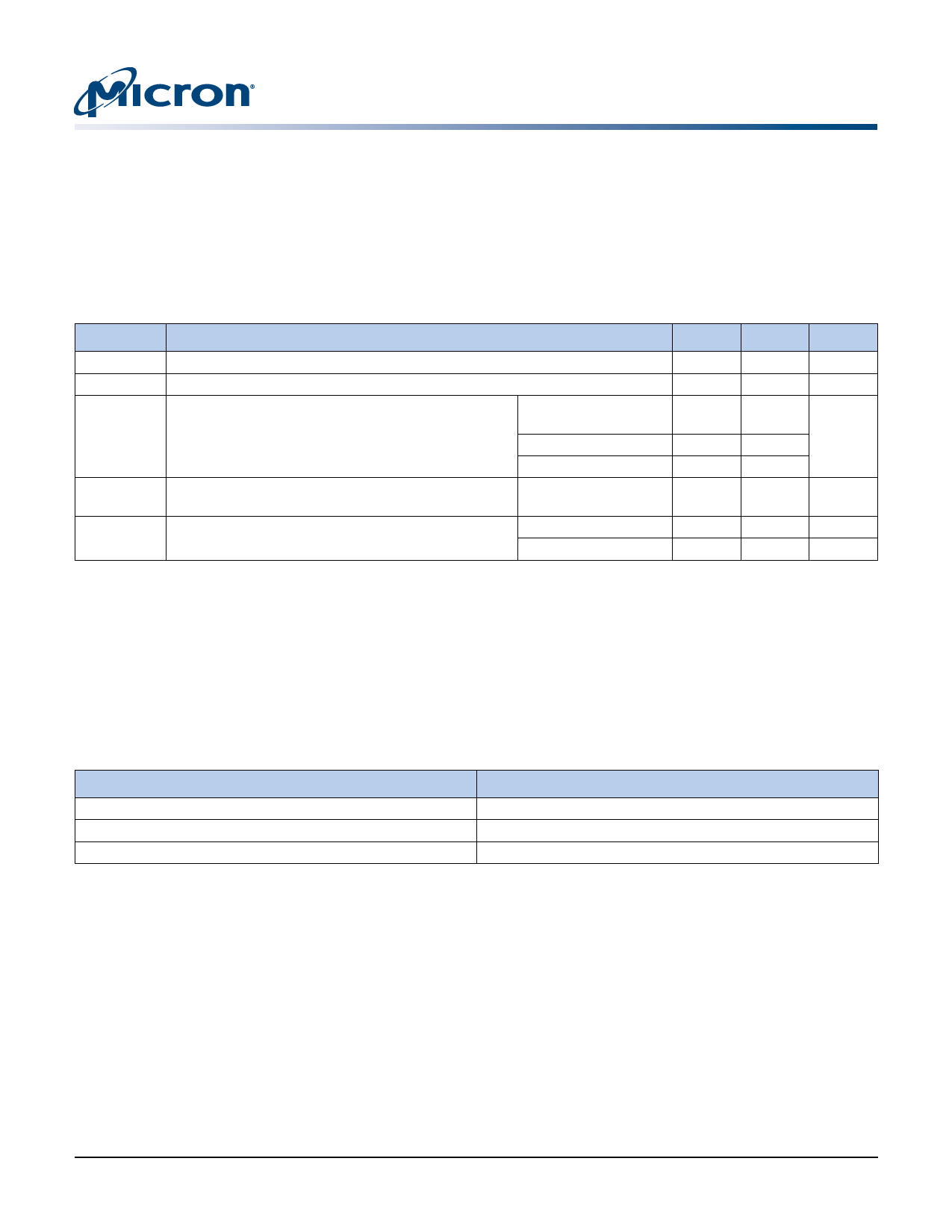
Table 7: Absolute Maximum Ratings
Symbol
VDD
VIN, VOUT
II
IOZ
TA
Parameter
VDD supply voltage relative to VSS
Voltage on any pin relative to VSS
Input leakage current; Any input 0V ≤ VIN ≤ VDD;
Address inputs,
VREF input 0V ≤ VIN ≤ 1.35V (All other pins not under RAS#, CAS#, WE#, BA
test = 0V)
S#, CKE, CK, CK#
DM
Output leakage current; 0V ≤ VOUT ≤ VDDQ; DQ are
disabled
DRAM ambient operating temperature1
DQ, DQS
Commercial
Industrial
Min
–1.0
–0.5
–32
–16
–4
–10
0
–40
Max
+3.6
+3.2
+32
+16
+4
+10
+70
+85
Units
V
V
µA
µA
°C
°C
Notes: 1. For further information, refer to technical note TN-00-08: “Thermal Applications,” available
on Micron’s Web site.
DRAM Operating Conditions
Recommended AC operating conditions are given in the DDR component data sheets.
Component specifications are available on Micron’s Web site. Module speed grades
correlate with component speed grades, as shown in Table 8.
Table 8:
Module and Component Speed Grades
DDR components may exceed the listed module speed grades
Module Speed Grade
-40B
-335
-265
Component Speed Grade
-5B
-6
-75
Design Considerations
Simulations
Micron memory modules are designed to optimize signal integrity through carefully
designed terminations, controlled board impedances, routing topologies, trace length
matching, and decoupling. However, good signal integrity starts at the system level.
Micron encourages designers to simulate the signal characteristics of the system’s
memory bus to ensure adequate signal integrity of the entire memory system.
Power
Operating voltages are specified at the DRAM, not at the edge connector of the module.
Designers must account for any system voltage drops at anticipated power levels to
ensure the required supply voltage is maintained.
PDF: 09005aef80a77a90/Source: 09005aef80a646bc
DDF16C64_128x64_L_H.fm - Rev. G 8/08 EN
9
Micron Technology, Inc., reserves the right to change products or specifications without notice.
©2003 Micron Technology, Inc. All rights reserved
Share Link: 