STK672-220-E Просмотр технического описания (PDF) - ON Semiconductor
Номер в каталоге
Компоненты Описание
производитель
STK672-220-E Datasheet PDF : 10 Pages
| |||
STK672-220-E
When operations of the MOSFET built into STK672-2** Series ICs is turned off for constant current chopping,
the ID signal falls like the waveform shown in the figure above. At this time, the output voltage, VDS, suddenly
rises due to electromagnetic induction generated by the motor coil.
In the case of voltage that rises suddenly, voltage is restricted by the MOSFET VDSS. Voltage restriction by
VDSS results in a MOSFET avalanche. During avalanche operations, ID flows and the instantaneous energy at
this time, EAVL1, is represented by Equation (1).
EAVL1=VDSS×IAVL×0.5×tAVL ------------------------------------------- (1)
VDSS: V units, IAVL: A units, tAVL: sec units
The coefficient 0.5 in Equation (1) is a constant required to convert the IAVL triangle wave to a
square wave.
During STK672-2** Series operations, the waveforms in the figure above repeat due to the constant current
chopping operation. The allowable avalanche energy, EAVL, is therefore represented by Equation (2) used to find
the average power loss, PAVL, during avalanche mode multiplied by the chopping frequency in Equation (1).
PAVL=VDSS×IAVL×0.5×tAVL×fc ------------------------------------------- (2)
fc: Hz units (fc is set to the PWM frequency of 50kHz.)
For VDSS, IAVL, and tAVL, be sure to actually operate the STK672-2** Series and substitute values when
operations are observed using an oscilloscope.
Ex. If VDSS=110V, IAVL=1A, tAVL=0.2μs when using a STK672-220-E driver, the result is:
PAVL=110×1×0.5×0.2×10-6×50×103=0.55W
VDSS=110V is a value actually measured using an oscilloscope.
The allowable loss range for the allowable avalanche energy value, PAVL, is shown in the graph in Figure 3.
When examining the avalanche energy, be sure to actually drive a motor and observe the ID, VDSS, and tAVL
waveforms during operation, and then check that the result of calculating Equation (2) falls within the allowable
range for avalanche operations.
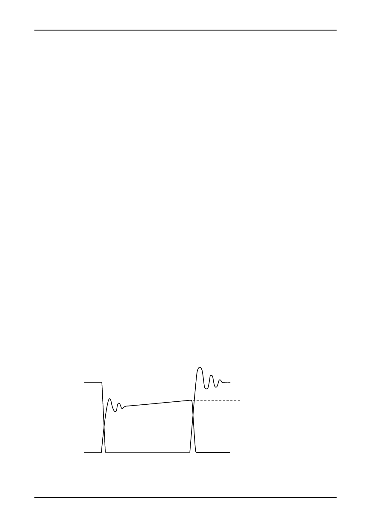
[ID and VDSS Operating Waveforms in Non-avalanche Mode]
Although the waveforms during avalanche mode are given in Figure 1, sometimes an avalanche does not result during
actual operations.
Factors causing avalanche are listed below.
• Poor coupling of the motor’s phase coils (electromagnetic coupling of A phase and AB phase, B phase and
BB phase).
• Increase in the lead inductance of the harness caused by the circuit pattern of the P.C. board and motor.
• Increases in VDSS, tAVL, and IAVL in Figure 1 due to an increase in the supply voltage from 24V to 36V.
If the factors above are negligible, the waveforms shown in Figure 1 become waveforms without avalanche as
shown in Figure 2.
Under operations shown in Figure 2, avalanche does not occur and there is no need to consider the allowable loss
range of PAVL shown in Figure 3.
VDS
IOH: Motor current peak value
ID
ITF02558
Figure 2 Output Current, ID, and Voltage, VDS, Waveforms 2 of the STK672-2** Series when Driving a
2-Phase Stepping Motor with Constant Current Chopping
No.7465-9/10
Share Link: 