S2ABF Просмотр технического описания (PDF) - Unspecified
Номер в каталоге
Компоненты Описание
производитель
S2ABF Datasheet PDF : 3 Pages
| |||
Trustworthy electronic circuit protection expert
Surface Mount General Purpose Silicon Rectifiers
S2ABF THRU S2MBF
S2ABF THRU S2MBF
Features
●For surface mounted applications
●Low profile package
●Glass Passivated Chip Junction
●Easy to pick and place
●Lead free in comply with EU RoHS 2011/65/EU directives
Mechanical Data
●Case: SMBF
●Terminals: Solderable per MIL-STD-750, Method 2026
●Approx. Weight: 57mg / 0.002oz
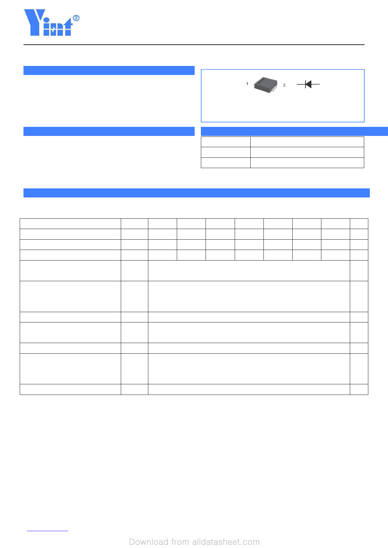
Simplified outline SMBF and symbol
Pinning
PIN
1
2
DESCRIPTION
Cathode
Anode
Absolute Maximum Ratings And Characteristics
Ratings at 25℃ ambient temperature unless otherwise specified.
Single phase, half wave, 60 Hz, resistive or inductive load. For capacitive load, derate current by 20%.
Parameter
Symbols S2ABF S2BBF
S2DBF
S2GBF
Maximum Repetitive Peak Reverse Voltage
VRRM
50
100
200
400
Maximum RMS voltage
VRMS
35
70
140
280
Maximum DC Blocking Voltage
VDC
50
100
200
400
Maximum Average Forward Rectified
IF(AV)
2
Current at Tc = 125 °C
Peak Forward Surge Current 8.3 ms Single
Half Sine Wave Superimposed on Rated
IFSM
50
Load
Maximum Forward Voltage at 1 A
VF
1.1
Maximum DC Reverse Current Ta = 25 °C
5
IR
at Rated DC Blocking Voltage Ta =125 °C
100
Typical Junction Capacitance (1)
Cj
25
RθJA
60
Typical Thermal Resistance (2)
RθJC
18
S2JBF
600
420
600
Operating and Storage Temperature Range Tj, Tstg
(1)Measured at 1 MHz and applied reverse voltage of 4 V D.C
(2)P.C.B. mounted with 2.0" X 2.0" (5 X 5 cm) copper pad areas.
-55 ~ +150
S2KBF
800
560
800
S2MBF
1000
700
1000
Units
V
V
V
A
A
V
μA
pF
℃/W
℃
www.yint.com.cn
1
Rev:19.3
Share Link: 