HCPL-8100 Просмотр технического описания (PDF) - HP => Agilent Technologies
Номер в каталоге
Компоненты Описание
производитель
HCPL-8100 Datasheet PDF : 11 Pages
| |||
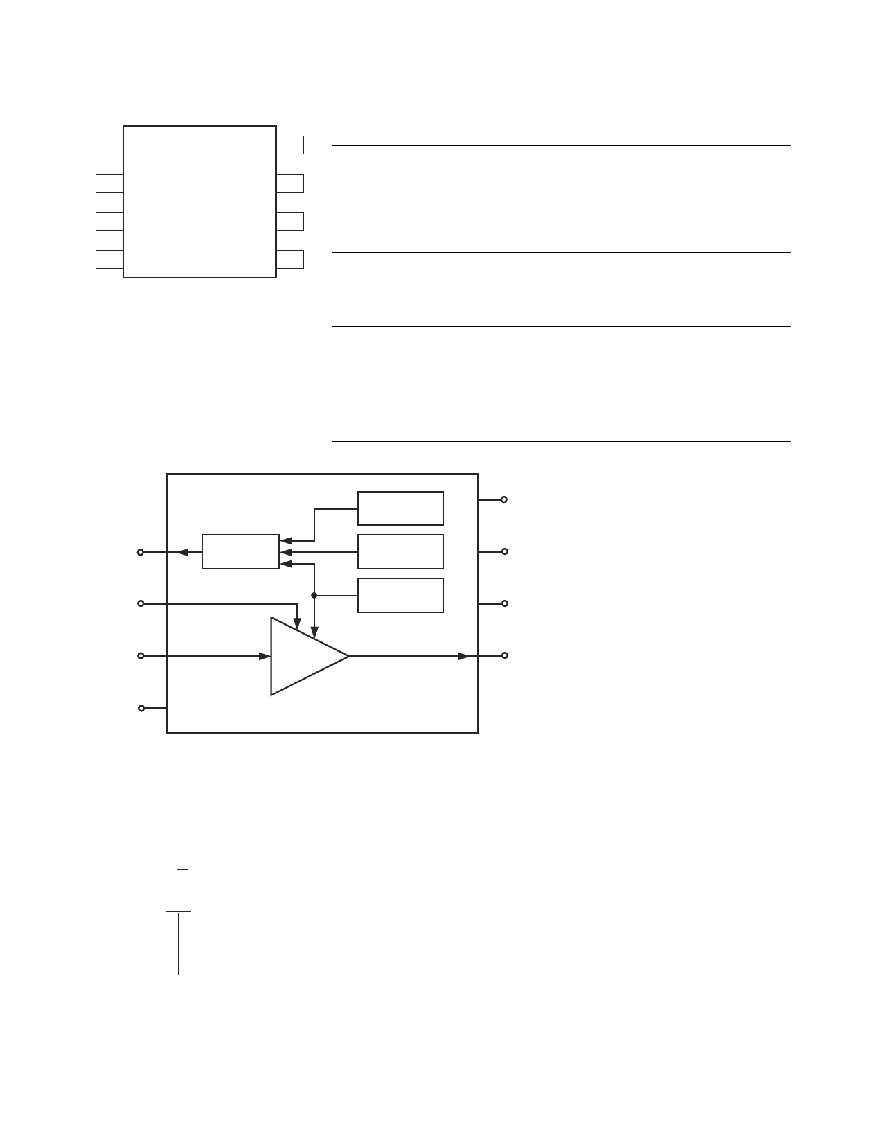
Package Pin Out
1 Status
2 Tx-en
3 Tx-in
4 R ref
Tx-out 8
VCC 7
GND 6
GND 5
Block Diagram
1
Status
2
Tx-en
Status
Output
Pin Descriptions
Pin No. Symbol
1
Status
2
Tx-en
3
Tx-in
4
Rref
5, 6 GND
7
VCC
8
Tx-out
Function
Description
Line condition
detection
A logic high indicates line conditions
such as
- under-voltage when VCC < 4 V
- load detection when ITx-out < −0.25 A
- over-temperature (thermal
shutdown)
Transmit enable A logic high enables the Tx-out;
A logic low disables the Tx-out and
changes it to high impedance state
Transmit input
Transmit signal input
Resistor reference Sets line driver biasing current,
typically 24 kΩ
Power supply ground Power supply and signal ground
5 V power supply 5 V power supply
Transmit output
Transmit signal output, to be enabled
by Tx-en
Under-Volt
Detection
Load
Detection
Over-Temp
Detection
7
VCC
6
GND
5
GND
3
Tx-in
Amp
8
Tx-out
Rref 4
Ordering Information
Specify part number followed by option number (if desired).
Example:
HCPL-8100 Standard 8-pin DIP package, 50 units per tube.
HCPL-0810-XXX
No option = SO-8 package, 100 units per tube.
500 = Tape and Reel Packaging Option, 1500 units per reel.
2
Share Link: 