TRC103 Просмотр технического описания (PDF) - Murata Manufacturing
Номер в каталоге
Компоненты Описание
производитель
TRC103 Datasheet PDF : 65 Pages
| |||
2.0 Functional Description
The TRC103 is a single-chip transceiver that can operate in the 863-870 and 902-928 MHz license-free bands,
and in the 950-960 MHz RFID band. The TRC103 supports two modulation schemes - FSK and OOK. The
TRC103’s highly integrated architecture requires a minimum of external components, while maintaining design
flexibility. All major RF communication parameters are programmable and most can be dynamically set. The
TRC103 is optimized for very low power consumption (3.3 mA typical in receiver mode). It complies with Europe-
an ETSI, FCC Part 15 and Canadian RSS-210 regulatory standards. Advanced digital features including the
TX/RX FIFO and the packet handling data mode significantly reduce the load on the host microcontroller.
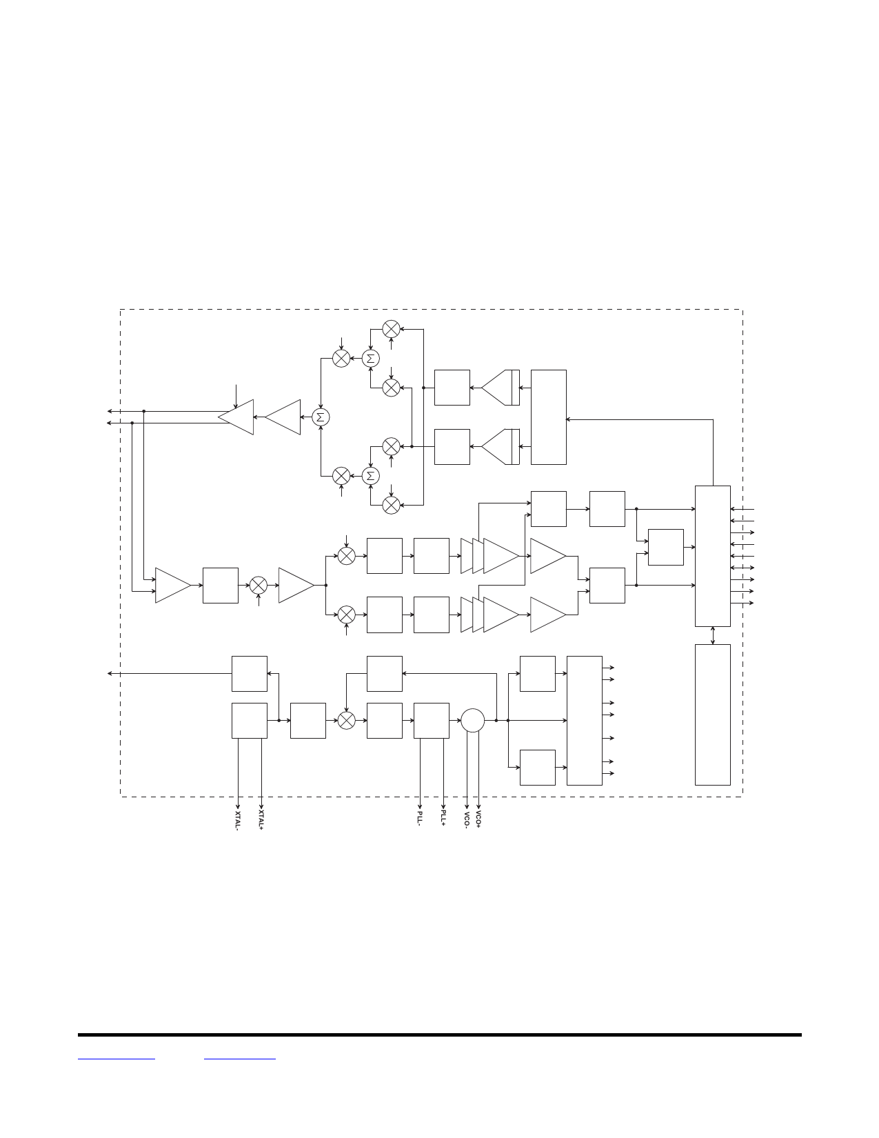
T R C 1 0 3 B lo c k D ia g r a m
R F+
R F-
C LK O U T
T X L O 1 -I
OOK
M o d u la tio n
In p u t
+
P ow er
Am p
D r iv e r
-
+
T X L O 2 -I
T X L O 2 -Q
-
+
T X L O 2 -I
T X L O 2 -Q
+
A n ti-
a lia s in g
F ilte r
A n ti-
a lia s in g
F ilte r
DAC
T r a n s m it
W a v e fo rm
G e n e ra to r
DAC
T X L O 1 -Q
RSSI
R e c e iv e r
LN A
B a n d -p a s s
VG A
F ilte r
R X LO 1
R X L O 2 -I
R -C
L o w -p a s s
F ilte r
B u tte rw o rth
or
P o ly p h a s e
F ilte r
IF A m p lifie r
L im ite r
R -C
L o w -p a s s
F ilte r
B u tte rw o rth
or
P o ly p h a s e
F ilte r
IF A m p lifie r
L im ite r
OOK
D e te c to r
FSK
D e te c to r
D a ta &
C lo c k
R e c o v e ry
C o n tro l
SCK
SDI
SDO
nS S _D A TA
n S S _ C O N F IG
D A TA
IR Q 1 /D C L K
IR Q 0
P LL_LO C K
R X L O 2 -Q
O s c illa to r
D iv id e r &
B u ffe r
VCO
F re q u e n c y
D iv id e r
D iv id e
by 8
T X L O 2 -I
T X L O 2 -Q
C ry s ta l
O s c illa to r
R e fe re n c e
F re q u e n c y
D iv id e r
P hase
D e te c to r
C h a rg e
Pum p
PLL
Loop
VCO
F ilte r
T X L O 1 -I
F IF O
I& Q
T X L O 1 -Q
P hase
R X LO 1
D iv id e
by 8
R X L O 2 -I
R X L O 2 -Q
Figure 1
The receiver is based on a superheterodyne architecture. It is composed of the following major blocks:
An LNA that provides low noise RF gain followed by an RF band-pass filter.
A first mixer which down-converts the RF signal to an intermediate frequency equal to 1/9 th of the carrier
frequency (about 100 MHz for 915 MHz signals).
A variable gain first IF preamplifier followed by two second mixers which down convert the first IF signal to
I and Q signals at a low frequency (zero-IF for FSK, low-IF for OOK).
www.RFM.com E-mail: info@rfm.com
© 2009-2010 by RF Monolithics, Inc.
Technical support +1.800.704.6079
Page 5 of 65
TRC103 - 11/29/12
Share Link: 