TRC103 Просмотр технического описания (PDF) - Murata Manufacturing
Номер в каталоге
Компоненты Описание
производитель
TRC103 Datasheet PDF : 65 Pages
| |||
2.5 Frequency Synthesizer
The Frequency Synthesizer generates the local oscillator (LO) signal for the receiver and transmitter sections.
The core of the synthesizer is implemented with an integer-N PLL architecture.
The frequency is set by three divider parameters R, P and S. R is the frequency divider ratio in the reference fre-
quency path. P and S set the frequency divider ratio in the feedback loop of the PLL. The frequency synthesizer
includes a crystal oscillator which provides the frequency reference for the PLL. The equations giving the rela-
tionships between the reference crystal frequency, the local oscillator frequency and RF carrier frequency are giv-
en below:
FLO = FXTAL*(75*(P + 1) + S)/(R + 1), with P and S in the range 0 to 255, S less than (P + 1), R in the
range 64 to 169, and FLO and FXTAL in MHz.
FRF = 1.125*FLO, where FRF and FLO are in MHz
FLO is the first local oscillator (VCO) frequency, FXTAL is the reference crystal frequency and FRF is the RF channel
frequency.
FLO is the frequency used for the first down-conversion of the receiver and the second up-conversion of the
transmitter. The intermediate frequency used for the second down-conversion of the receiver and the first up-
conversion of the transmitter is equal to 1/8 of FLO. As an example, with a crystal frequency of 12.8 MHz and an
RF frequency of 869 MHz, FLO is 772.4 MHz and the first IF of the receiver is 96.6 MHz.
There are two sets of divider ratio registers: SynthR1[7..0], SynthP1[7..0], SynthS1[7..0], and SynthR2[7..0],
SynthP2[7..0], SynthS2[7..0]. The MCFG00_RF_Frequency[0] bit is used to select which set of registers to use
as the current frequency setting. For frequency hopping applications, this reduces the programming and synthe-
sizer settling time when changing frequencies. While the data is being transmitted, the next frequency is pro-
grammed and ready. When the current transaction is complete, the MCFG00_RF_Frequency[0] bit is comple-
mented and the frequency shifts to the next freq according to the contents of the divider ratio registers. This pro-
cess is repeated for each frequency hop.
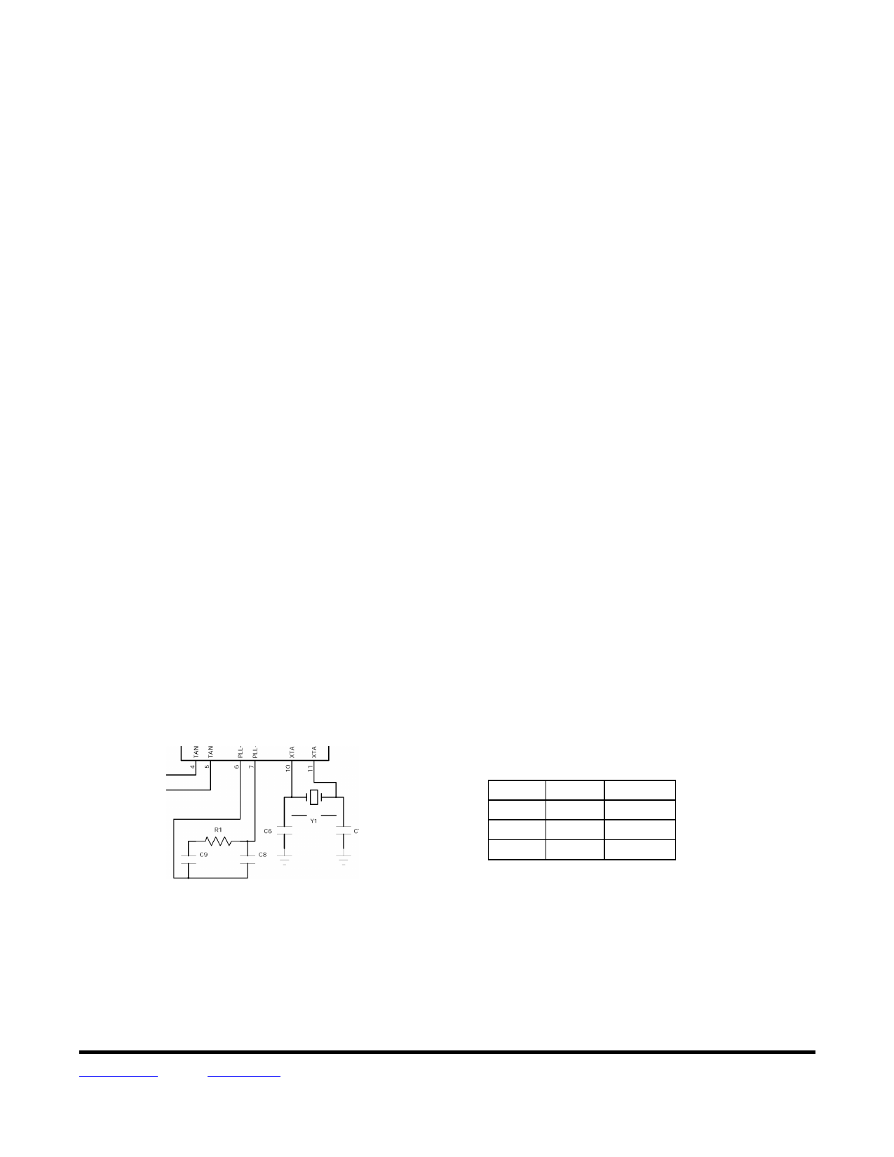
2.6 PLL Loop Filter
The loop filter for the frequency synthesizer is shown in Figure 6.
PLL Loop Filter
Figure 6
PLL Loop Filter Components
Name
C8
C9
R1
Value
1000 pF
6800 pF
6.8 kΩ
Tolerance
±10%
±10%
±5%
Table 4
Typical recommended component values for the frequency synthesizer loop filter are provided in Table 4 above.
The loop filter settings are not dependent on the frequency band, so they can be universally used on all designs.
PLL lock status can be provided on Pin 23 by setting the IRQCFG0E_PLL_LOCK_EN[0] bit to a 1 (default).
When the PLL is locked Pin 23 (PLL_LOCK) is high, and when the PLL is unlocked Pin 23 is low. The lock status
of the PLL can also be checked by reading the IRQCFG0E_PLL_LOCK_ST[1] bit. Note that this bit latches high
each time the PLL locks and must be reset by writing a 1 to it.
www.RFM.com E-mail: info@rfm.com
© 2009-2010 by RF Monolithics, Inc.
Technical support +1.800.704.6079
Page 10 of 65
TRC103 - 11/29/12
Share Link: 