CRD4525 Просмотр технического описания (PDF) - Cirrus Logic
Номер в каталоге
Компоненты Описание
производитель
CRD4525 Datasheet PDF : 91 Pages
| |||
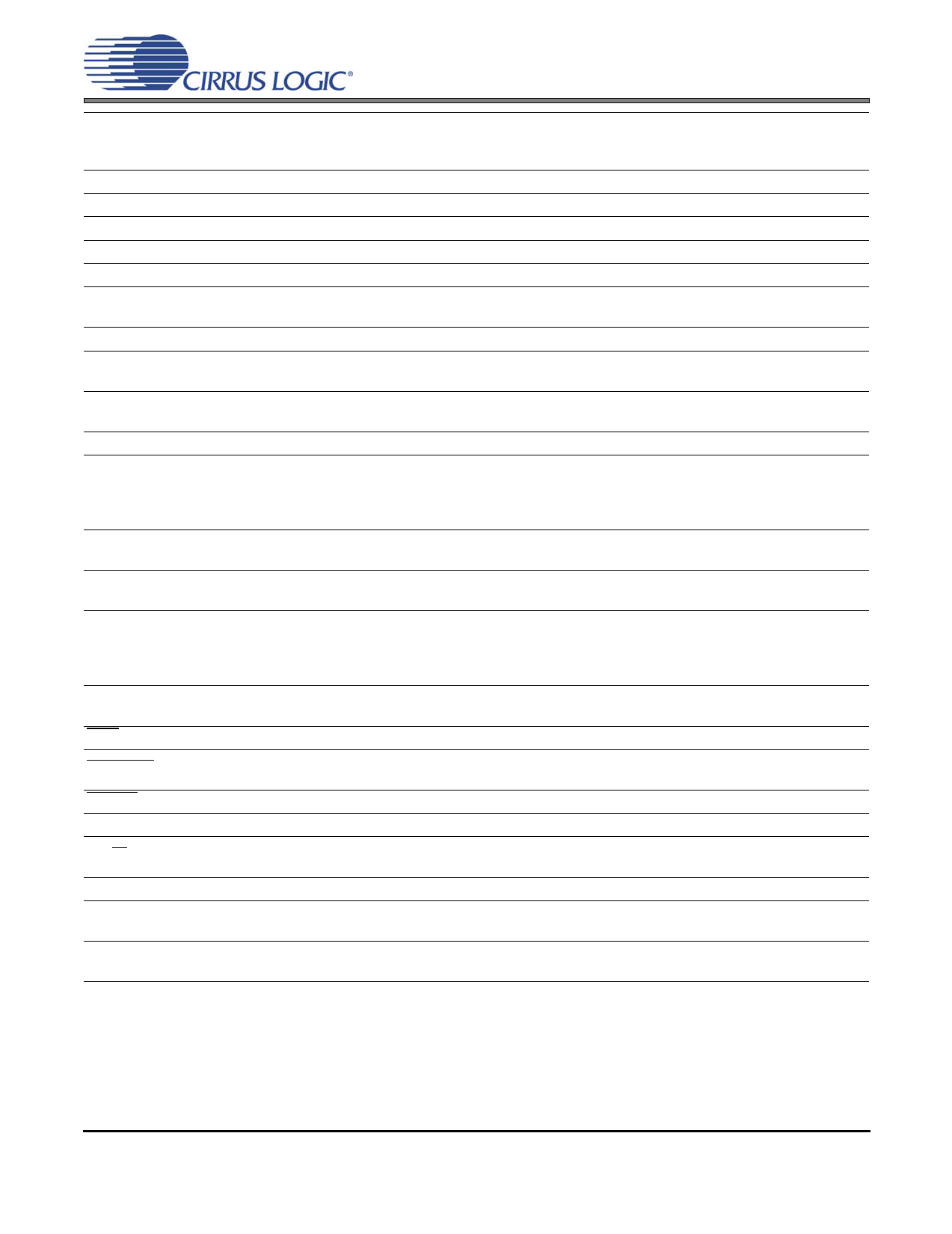
LVD
DGND
VD_REG
VD
VA_REG
AGND
FILT+
VQ
AFILTL
AFILTR
AINL
AINR
OCREF
PGND
RAMP_CAP
VP
OUT4
OUT3
OUT2
OUT1
PWM_SIG2
PWM_SIG1
TWR
ERRUVTE
ERROC
EN_TFB
I2S/LJ
SYS_CLK
TSTO
TSTI
CS4525
VD Voltage Level Indicator (Input) - Identifies the voltage level attached to VD. When applying
9 5.0 V to VD, LVD must be connected to VD. When applying 2.5 V or 3.3 V to VD, LVD must be con-
nected to DGND.
10 Digital Ground (Input) - Ground for the internal logic and I/O.
11 Core Logic Power (Output) - Internally generated low voltage power supply for digital logic.
12 Digital Power (Input) - Positive power supply for the internal regulators and digital I/O.
13 Analog Power (Output) - Internally generated positive power for the analog section and I/O.
14 Analog Ground (Input) - Ground reference for the internal analog section and I/O.
15
Positive Voltage Reference (Output) - Positive reference voltage for the internal ADC sampling
circuits.
16 Common Mode Voltage (Output) - Filter connection for internal common mode voltage.
17
18
Antialias Filter Connection (Output) - Antialias filter connection for ADC inputs.
19 Analog Input (Input) - The full-scale input level is specified in the ADC Analog Characteristics
20 specification table.
21 Over Current Reference Setting (Input) - Sets the reference for over current detection.
22,23
27,28
33,34
37,38
Power Ground (Input) - Ground for the individual output power half-bridge devices.
24
Output Ramp Capacitor (Input) - Used for shaping the output ramp time for half-bridge configured
outputs.
25,30,
31,36
High Voltage Power (Input) - High voltage power supply for the individual half-bridge devices.
26
29
32
PWM Output (Output) - Amplified PWM power outputs.
35
39
40
PWM Output (Output) - PWM switching signals.
41 Thermal Warning Output (Output) - Thermal warning output.
42
Thermal and Undervoltage Error Output (Output) - Error flag for thermal shutdown and under-
voltage.
43 Overcurrent Error Output (Output) - Overcurrent error flag.
44 Enable Thermal Feedback (Input) - Enables the thermal foldback feature when high.
45
I²S/Left Justified (Input) - Selects between I²S and Left-Justified data format for the serial input
and output ports. Selects I²S when high and LJ when low.
46 System Clock (Input/Output) -Clock source for the delta-sigma modulators.
47
Test Output (Output) - This pin is an output used for the crystal oscillator driver available only in
software mode. It must be left unconnected for normal hardware mode operation.
48
Test Input (Input) - This pin is an input used for the crystal oscillator driver available only in soft-
ware mode. It must be tied to digital ground for normal hardware mode operation.
DS726A1
11
Share Link: 