MC33794 Просмотр технического описания (PDF) - Freescale Semiconductor
Номер в каталоге
Компоненты Описание
производитель
MC33794 Datasheet PDF : 18 Pages
| |||
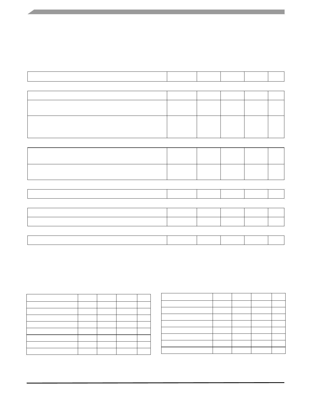
DYNAMIC ELECTRICAL CHARACTERISTICS
Table 4. Dynamic Electrical Characteristics
Characteristics noted under conditions 9.0 V ≤ VPWR ≤ 18 V, -40°C ≤ TA ≤ 85°C unless otherwise noted. Typical values noted
reflect the approximate parameter means at TA = 25°C under normal conditions unless otherwise noted. Voltages are relative
to GND unless otherwise noted.
Characteristic
Symbol
Min
Typ
Max
Unit
OSC
OSC Frequency Stability (12), (13)
OSC Center Frequency
R_OSC = 39 kΩ
Harmonic Content (12)
2nd through 4th Harmonic Level
5th and Higher
f STAB
–
f OSC
–
OSCHARM
–
–
–
10
%
kHz
120
–
dB
–
-20
–
-60
Shield Driver
Shield Driver Maximum Harmonic level below Fundamental (12)
10 pF ≤ CLOAD ≤ 500 pF
Shield Driver Gain Bandwidth Product (12)
Measured at 120 kHz
SDHARM
dB
–
-20
–
SDGBW
MHz
–
4.5
–
POR
POR Time-Out Period
Watchdog
t PER
9.0
–
50
ms
Watchdog Time-Out Period
Watchdog Reset Hold Time
Lamp Driver
t WDPER
50
68
250
ms
t WDHLD
9.0
–
50
ms
Short Circuit to Battery Survival Time
t SCB
3.0
–
Notes
12. Verified by design and characterization. Not tested in production.
13. Does not include errors in external reference parts.
–
ms
ELECTRODE SELECTION
Table 5. Electrode Selection
TERMINAL/SIGNAL
D
C
B
A
Source (internal)
E1
E2
E3
E4
E5
E6
E7
0
0
0
0
0
0
0
1
0
0
1
0
0
0
1
1
0
1
0
0
0
1
0
1
0
1
1
0
0
1
1
1
Table 5. Electrode Selection (continued)
TERMINAL/SIGNAL
D
C
B
A
E8
1
0
0
0
E9
1
0
0
1
REF_A
1
0
1
0
REF_B
1
0
1
1
Internal OSC
1
1
0
0
Internal OSC after 22 kΩ
1
1
0
1
Internal Ground
1
1
1
0
Reserved
1
1
1
1
MC33794
10
Sensors
Freescale Semiconductor
Share Link: 