MT88V32 Просмотр технического описания (PDF) - Mitel Networks
Номер в каталоге
Компоненты Описание
производитель
MT88V32 Datasheet PDF : 14 Pages
| |||
Preliminary Information
MT88V32
Functional Description
The state of the MT88V32 8 X 4 switching matrix is
updated through a simple parallel processor
interface. This interface provides access to 32 two
stage latches, which determines the state (open/
close) of each switching array node. Each latch (or
node) is addressed by the AX0-AX1 and AY0-AY2
inputs as per Table 2, and the DATA input will
determine if the connection is to be made (DATA=1)
or opened (DATA=0).
The second stage of the two stage latches controls
the current state of each switching node. The value
held in the first stage is the input to the second
stage. This allows the device to be programmed in
two ways. That is, individual switching nodes may be
updated one at a time, or all nodes may be updated
at once.
To update one node at a time the STROBE2 input
should be held low. This makes the second stage
latches transparent and the matrix immediately
reflects the state of the first stage latches. A write
cycle example follows:
1) STROBE2 is low,
2) CS and R/W are low, MR is high,
3) AX0-AX1 and AY0-AY2 as per Table 2,
4) DATA input high to close or low to open, and
5) STROBE1 toggled from high-to-low-to-high.
These steps (one write cycle) may be repeated for
each switch state change. This can also be
accomplished by holding STROBE1 low and toggling
STROBE2. See Figure 14 for timing.
To update all nodes simultaneously all switch state
changes must be written into the first stage latches.
This is accomplished by holding STROBE2 high and
performing steps 2) through 5) above for each
switching node that is to be changed. Writing to the
first stage latches only will not affect the switching
state of the matrix. When the changes have been
made all the switches of the matrix may be updated
simultaneously by toggling the STROBE2 input from
high-to-low-to high.
When STROBE2 is used to update the state of the
MT88V32 all switch “breaks” are completed before
any switch “makes” occur. There is approximately
10ns delay between “breaks” and “makes”.
Both the first and second stage latches will be
cleared when the master reset (MR) is taken from
high-to-low. This will open all the switch nodes. The
operation of MR is independent of CS, AX0-AX1,
AY0-AY2 and R/W.
The status of each switching array node (second
stage latch) can be read through the bidirectional
DATA pin. A read cycle example follows:
1) CS is low, R/W and MR are high,
2) AX0-AX1 and AY0-AY2 as per Table 2, and
3) DATA output high for closed or low for open.
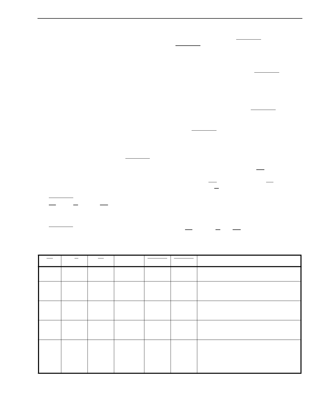
MR
R/W
CS
DATA
STROBE1 STROBE2
DATA
1
0
1
0
1
0
1
0
1
0
1→ 0
0
1
1→ 0
0
0
0
0
1→ 0→ 1
0
1
No Change to 1st stage latch.
1
1st stage latch is loaded with data.
1
1st stage latch is transparent.
1
Selected latch is cleared and set again (i.e.,
output follows input).
1
0
0
1
0
x
1
0
x
1
0
0
1
0→ 1
1
1st stage latch output is frozen.
x
1
1→ 0
Output of 1st stage latch is transferred to
output of 2nd stage latches.
x
1
0→1
2nd stage latch output is frozen.
x
0
0
Both 1st stage and 2nd stage latches are
transparent.
1
1
0
0
x
x
DATA becomes an output and reflects the
contents of the 2nd stage latch addressed
by AX0-AX1 and AY0-AY2.
0
1
1
1
1
1
All crosspoints opened (data in 1st and 2nd
stage latches are cleared).
Table 1 - Truth Tables
Note: x = don’t care, 0 = logic "0" state, 1 = logic "1" state
A logic 1 on DATA input closes a connection.
A logic 0 on DATA input opens a connection.
3-53
Share Link: 