IL4116 Просмотр технического описания (PDF) - Siemens AG
Номер в каталоге
Компоненты Описание
производитель
IL4116 Datasheet PDF : 3 Pages
| |||
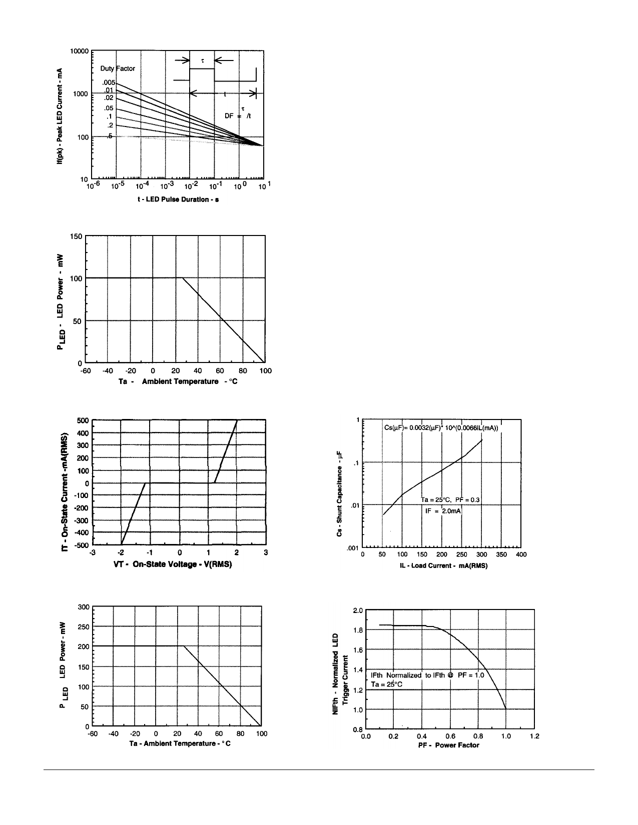
Figure 3. Peak LED current vs. duty factor, Tau
Figure 4. Maximum LED power dissipation
Power Factor Considerations
A snubber isn’t needed to eliminate false operation of the
TRIAC driver because of the IL411’s high static and commutat-
ing dv/dt with loads between 1 and 0.8 power factors. When
inductive loads with power factors less than 0.8 are being
driven, include a RC snubber or a single capacitor directly
across the device to damp the peak commutating dv/dt spike.
Normally a commutating dv/dt causes a turning-off device to
stay on due to the stored energy remaining in the turning-off
device.
But in the case of a zero voltage crossing optotriac, the com-
mutating dv/dt spikes can inhibit one half of the TRIAC from
turning on. If the spike potential exceeds the inhibit voltage of
the zero cross detection circuit, half of the TRIAC will be held-
off and not turn-on. This hold-off condition can be eliminated by
using a snubber or capacitor placed directly across the optot-
riac as shown in Figure 7. Note that the value of the capacitor
increases as a function of the load current.
The hold-off condition also can be eliminated by providing a
higher level of LED drive current. The higher LED drive pro-
vides a larger photocurrent which causer. the phototransistor to
turn-on before the commutating spike has activated the zero
cross network. Figure 8 shows the relationship of the LED drive
for power factors of less than 1.0. The curve shows that if a
device requires 1.5 mA for a resistive load, then 1.8 times (2.7
mA) that amount would be required to control an inductive load
whose power factor is less than 0.3.
Figure 5. On-state terminal voltage vs. terminal current
Figure 7. Shunt capacitance versus load current
versus power factor
Figure 6. Maximum output power dissipation
Figure 8. Normalized LED trigger current
IL4116/4117/4118
5–3
Share Link: 