BC818W Просмотр технического описания (PDF) - Diotec Semiconductor Germany
Номер в каталоге
Компоненты Описание
производитель
BC818W Datasheet PDF : 2 Pages
| |||
BC817W ... BC818W
Characteristics 2)
DC current gain – Kollektor-Basis-Stromverhältnis 1)
Tj = 25°C
VCE = 1 V, IC = 100 mA
Group -16
Group -25
hFE
Group -40
VCE = 1 V, IC = 500 mA
hFE
Collector-Emitter saturation voltage – Kollektor-Emitter-Sättigungsspg. 4)
IC = 500 mA, IB = 50 mA
Base-Emitter-voltage – Basis-Emitter-Spannung 1)
VCEsat
VCE = 1 V, IC = 500 mA
VBE
Collector-Base cutoff current – Kollektor-Basis-Reststrom
VCB = 20 V, (E open)
ICBO
Emitter-Base cutoff current – Emitter-Basis-Reststrom
VEB = 5 V, (C open)
IEBO
Gain-Bandwidth Product – Transitfrequenz
VCE = 5 V, IC = 10 mA, f = 100 MHz
fT
Collector-Base Capacitance – Kollektor-Basis-Kapazität
VCB = 10 V, IE =ie = 0, f = 1 MHz
CCBO
Thermal resistance junction to ambient
Wärmewiderstand Sperrschicht – Umgebung
RthA
Min.
Kennwerte 2)
Typ.
Max.
100
–
250
160
–
400
250
–
600
40
–
–
–
–
0.7 V
–
–
1.2 V
–
–
100 nA
–
–
100 nA
100 MHz
–
–
–
–
5 pF
< 625 K/W .2)
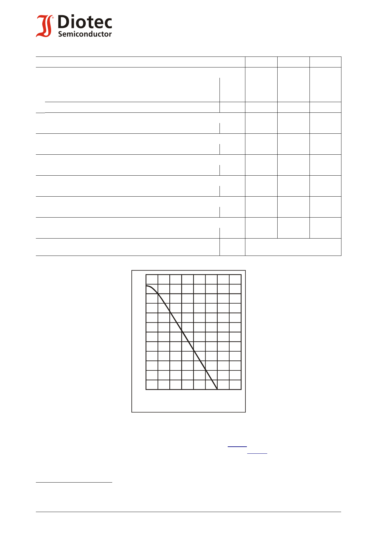
120
[%]
100
80
60
40
20
Ptot
0
0 TA 50
100
150 [°C]
Power dissipation versus ambient temperature 1)
Verlustleistung in Abh. von d. Umgebungstemp.1)
Disclaimer: See data book page 2 or website
Haftungssauschluss: Siehe Datenbuch Seite 2 oder Internet
1 Tested with pulses tp = 300 µs, duty cycle ≤ 2% – Gemessen mit Impulsen tp = 300 µs, Schaltverhältnis ≤ 2%
2 Mounted on P.C. board with 3 mm2 copper pad at each terminal
Montage auf Leiterplatte mit 3 mm2 Kupferbelag (Lötpad) an jedem Anschluss
2
http://www.diotec.com/
© Diotec Semiconductor AG
Share Link: 