LTC1877 Просмотр технического описания (PDF) - Linear Technology
Номер в каталоге
Компоненты Описание
производитель
LTC1877 Datasheet PDF : 16 Pages
| |||
LTC1877
APPLICATIONS INFORMATION
mized to provide stable high performance transient
response regardless of the output capacitor selected.
ESR is a direct function of the volume of the capacitor.
Manufacturers such as Taiyo Yuden, AVX, Sprague, Kemet
and Sanyo should be considered for high performance
capacitors. The POSCAP solid electrolytic capacitor avail-
able from Sanyo is an excellent choice for output bulk
capacitors due to its low ESR/size ratio. Once the ESR
requirement for COUT has been met, the RMS current
rating generally far exceeds the IRIPPLE(P-P) requirement.
When using tantalum capacitors, it is critical that they are
surge tested for use in switching power supplies. A good
choice is the AVX TPS series of surface mount tantalum,
available in case heights ranging from 2mm to 4mm. Other
capacitor types include KEMET T510 and T495 series and
Sprague 593D and 595D series. Consult the manufacturer
for other specific recommendations.
Output Voltage Programming
The output voltage is set by a resistive divider according
to the following formula:
VOUT = 0.8V1+ RR21
(2)
The external resistive divider is connected to the output,
allowing remote voltage sensing as shown in Figure 3.
0.8V ≤ VOUT ≤ 10V
R2
VFB
LTC1877
GND
R1
1877 F03
Figure 3. Setting the LTC1877 Output Voltage
Phase-Locked Loop and Frequency Synchronization
The LTC1877 has an internal voltage-controlled oscillator
and phase detector comprising a phase-locked loop. This
allows the top MOSFET turn-on to be locked to the rising
edge of an external frequency source. The frequency range
of the voltage-controlled oscillator is 400kHz to 700kHz.
The phase detector used is an edge sensitive digital type
that provides zero degrees phase shift between the exter-
nal and internal oscillators. This type of phase detector will
not lock up on input frequencies close to the harmonics of
the VCO center frequency. The PLL hold-in range ∆fH is
equal to the capture range, ∆fH = ∆fC = ±150kHz.
The output of the phase detector is a pair of complemen-
tary current sources charging or discharging the external
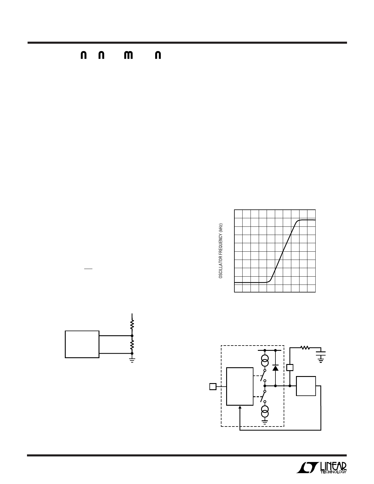
filter network on the PLL LPF pin. The relationship
between the voltage on the PLL LPF pin and operating
frequency is shown in Figure 4. A simplified block diagram
is shown in Figure 5.
If the external frequency (VSYNC/MODE) is greater than
550kHz, the center frequency, current is sourced continu-
ously, pulling up the PLL LPF pin. When the external
800
700
600
500
400
300
0
0.4
0.8
1.2
1.6
2.0
VPLL LPF (V)
1877 • F04
Figure 4. Relationship Between Oscillator
Frequency and Voltage at PLL LPF Pin
PHASE
2.4V
DETECTOR
SYNC/
MODE
DIGITAL
PHASE/
FREQUENCY
DETECTOR
RLP
CLP
PLL LPF
VCO
1877 F05
Figure 5. Phase-Locked Loop Block Diagram
10
Share Link: 