HMP8112A Просмотр технического описания (PDF) - Harris Semiconductor
Номер в каталоге
Компоненты Описание
производитель
HMP8112A Datasheet PDF : 40 Pages
| |||
HMP8112A
AMPLITUDE
AMPLITUDE
Y
I, Q
Y
fH/2
fH/2
fH
FREQUENCY
Y
I, Q
Y
255
WHITE 255
BLUE 255
RED
248
100% 240
100% 240
100%
212
BLUE
75%
212
RED
75%
128
128
128
44
YELLOW
75%
44
CYAN
75%
16
BLACK 16
0
YELLOW
100%
16
0
CYAN
100%
Y DATA
RANGE
Cb DATA
RANGE
Cr DATA
RANGE
FIGURE 7. YCbCr DATA RANGES
The decoder is compatible with all NTSC and PAL video for-
mats available throughout the world. Table 2 shows the com-
patible video standards.
FREQUENCY
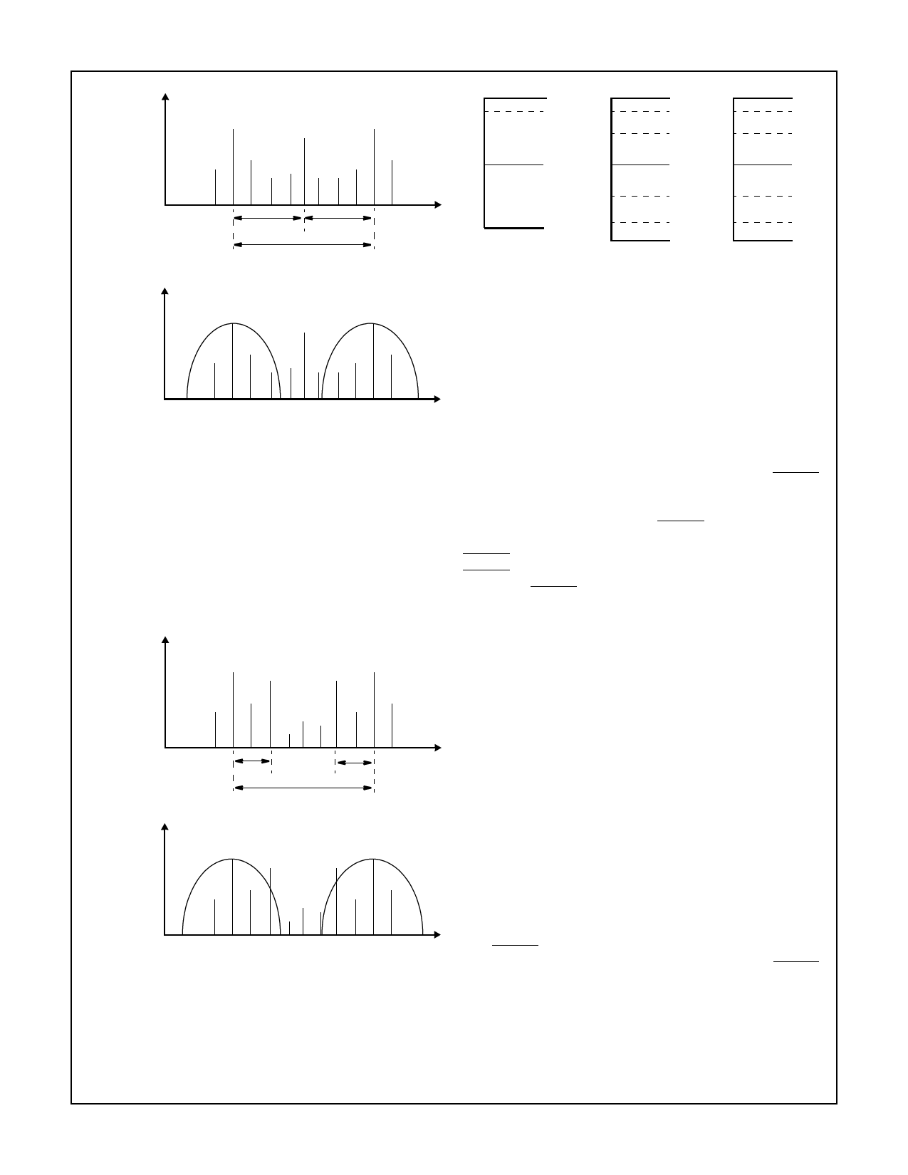
FIGURE 5. COMPOSITE NTSC INTERLEAVE SCHEME
For PAL systems there are 283.75 cycles of chrominance
per line. Chrominance information is spaced at quarter line
intervals with a reference phase of 135o. The reference
phase alternates from line to line by 90o. To fully separate
the PAL chrominance and luminance signals the user select-
able filters should be enabled. The chroma notch filter built
into the luminance channel should be enabled for PAL sys-
tems to reduce cross luminance effects. The low pass filter in
the chrominance processing chain helps to reduce cross
color products.
Horizontal Sync Detection
Horizontal sync is detected in the Output Sample Rate con-
verter (OSR). The OSR spatially aligns the pixels in the verti-
cal direction by using the horizontal sync information
embedded in the digital video data stream. The HSYNC
sync pulse out of the decoder is a video synchronous output
pin. This signal follows the horizontal sync of an input video
source. If there is no source the HSYNC pin will continue to
run at video rates due to the Line Locked PLL free-running.
HSYNC can be moved throughout the video line using the
HSYNC Start and End time registers. This 10-bit register
allows the HSYNC to be moved in OSR clock increments
(12.27MHZ, 13.5MHz or 14.75MHz).
AMPLITUDE
Y I, Q
I, Q
Y
AMPLITUDE
fH/4
fH/4
fH
FREQUENCY
Y
I, Q
I, Q
Y
FREQUENCY
FIGURE 6. COMPOSITE PAL INTERLEAVE SCHEME
The demodulator in the decoder decodes the color compo-
nents into U and V. The U and V components are converted
to Cb and Cr components after the decoding process.
YCbCr has a usable data range as shown in Figure 7. The
data range for Y is limited to a minimum of 16.
Vertical Sync and Field Detection
The vertical sync and field detect circuit of the decoder uses
a low time counter to detect the vertical sync sequence in
the video data stream. The low time counter accumulates
the low time encounted after the horizontal sync edge or at
the start of each line. When the low time count exceeds the
vertical sync detect threshold, VSYNC is asserted immedi-
ately. VSYNC will remain asserted for a minimum of 1 line.
The FIELD flag is updated at the same time as the VSYNC
line. The FIELD pin is a ‘0’ for ODD fields and a ‘1’ for even
fields.
In the case of lost vertical sync or excessive noise that would
prevent the detection of vertical sync, the FIELD flag will
continue to toggle. Lost vertical sync is declared if after 337
lines a vertical sync period was not detected for 3 successive
lines. When this occurs the phase locked loops are initialized
to the acquisition state.
The VSYNC pulse out of the decoder follows the vertical
sync detection and is typically 6.5 lines long. The VSYNC
will run at the field rate of the selected video standard
selected. For NTSC the field rate is 60Hz and for PAL the
field rate is 50Hz. This signal will continue to run even in the
event of no incoming video signal.
4-7
Share Link: 